


Addressable Pixel LEDs: Programming WS2812B and SK6812 with SPI Controller
In the universe of modern lighting, addressable LEDs represent a true technological revolution: they are not simple light sources, but genuine intelligent pixels capable of transforming any surface, architecture, or installation into a dynamic display, controllable with absolute precision, pixel by pixel, in real time. The ability to manage each individual light point independently (assigning it a specific color from over 16 million possibilities, precise intensity, and time-based behavior) opens up scenarios that until a few years ago were reserved for film productions, television studios, or worldwide musical events. Today, thanks to the expansion of pixel technologies and the availability of professional solutions, anyone (from interior architects to experienced installers, from event industry entrepreneurs to passionate makers) can access this level of lighting control with accessible costs and complexity.
At the heart of this technology are the WS2812B and SK6812 chips, two of the most widespread and capable integrated circuits on the market, capable of receiving and processing high-speed digital commands through a serial communication protocol. Their widespread adoption has become the standard for addressable pixel LED strips, opening up a vast ecosystem of software tools, libraries, hardware controllers, and practical applications. Understanding how they work, how to program them, and how to integrate them into a professional lighting system is the starting point for creating truly extraordinary installations.
In this guide, designed both for lighting designers seeking advanced solutions and for technicians installing and configuring a system for the first time, we will explore every aspect of addressable LEDs: from the physics of their operation to control architectures, from communication protocols to practical programming via SPI controllers, to selecting the right products and best practices for safe, efficient, and long-lasting installations.
In this article...
- What are addressable LEDs: definition, history, and operating principles
- The RGB LED pixel: anatomy, internal structure, and colors
- Types of chips for addressable LEDs: WS2812B, SK6812, WS2818, WS2814, and others
- Addressable pixel LED strips: characteristics, density, and product types
- The SPI controller for addressable LEDs: what it is, how it works, and how to use it
- How to program WS2812B LED strips: complete operational guide
- How to program SK6812 LED strips: configuration and advanced specifications
- The Skydance SPI ecosystem: WiFi controllers, DMX, and staircase automation
- Technical configuration guide: IC type, RGB order, and pixel length
- Powering addressable LED strips: calculations, voltage drop, and safety
- Applications of addressable LEDs: professional and creative scenarios
- Dimmable LEDs and addressable LEDs: differences and integration
- Software and libraries for programming with SPI controllers: FastLED, Adafruit NeoPixel, Tuya
- Practical installation of an addressable LED strip: tools, connections, and configuration
- Maintenance and troubleshooting for addressable pixel LED strips
- Regulatory aspects: use of addressable LEDs in Italy and regulations
- Market and costs: data, statistics, and budgeting for addressable LED projects
- Addressable LED products from Ledpoint.it: catalog and professional solutions
- FAQ: frequently asked questions about addressable pixel LEDs
- Conclusions: choosing the right addressable LEDs for every project
What are addressable LEDs: definition, history, and operating principles
Before delving into the technical details of programming with SPI controllers and the specific protocols of WS2812B and SK6812 chips, it is essential to build a solid and thorough understanding of what addressable LEDs actually are and why they represent such a significant qualitative leap compared to traditional LEDs. An addressable LED is a device that integrates, within the same physical LED package, an electronic control circuit called an IC (Integrated Circuit) or driver chip capable of receiving digital commands, interpreting them, and translating them into electrical signals that drive the red, green, and blue (and sometimes white) emissive components. The word "addressable" derives precisely from the ability to assign each individual LED or group of LEDs a unique address in the data chain, allowing the control system to communicate with each component individually.
How addressable LEDs work: the daisy chain
The fundamental principle that distinguishes an addressable LED from any other LED is the daisy chain architecture: LEDs are connected in series on the data signal, but in parallel on the power supply. When the controller sends a data packet on the line, the first LED in the chain reads its own bits, interprets them, updates its color and brightness, and then retransmits the remaining bits to the next LED. This digital shift register mechanism propagates along the entire strip in a few microseconds, allowing the entire strip to be updated at frequencies typically between 400 Hz and 800 Hz.
The typical control signal for chips like the WS2812B is called NZR (Non-Return-to-Zero): it consists of variable-duration pulses on a single data wire, where the duration of the high pulse determines whether the bit is "1" or "0". Each LED consumes 24 bits of data (8 bits for each of the R, G, B channels), or 32 bits for RGBW models, and then retransmits everything that follows to the next node. This means that to control a strip of 100 WS2812B LEDs, the controller must send a packet of 2400 consecutive bits (100 × 24 bits), then wait for a reset signal (pause of at least 50 µs) before the next update.
Brief history of addressable LEDs
The history of addressable LEDs begins in the early 2000s, when Asian semiconductor manufacturers began integrating the first driver ICs into SMD LED packages. The real turning point came with the launch of the WS2801 chip (WorldSemi, around 2010), the first chip for addressable LED strips with a two-wire SPI interface (clock + data) to achieve significant commercial distribution. Shortly after, in 2012, the same company presented the revolutionary WS2812 (and then WS2812B in 2013): the first version to eliminate the clock wire, reducing the connection to just the data wire and greatly simplifying wiring and control. This chip quickly became the global standard, fueling the DIY, maker, and professional ecosystem we know today, with millions of units sold annually worldwide.
In subsequent years, evolution did not stop: chips like the SK6812 (Opsco, 2015) introduced the RGBW version with an additional white channel, the WS2814 brought pixel control to 24V RGBW systems, the WS2818 improved robustness with differential signals, and the APA102 (Shenzhen LED Color Lighting) introduced the two-wire SPI protocol for high-speed applications. Each generation responded to specific market needs (higher density, better white, higher voltages, more robust signals), building a rich and constantly evolving technological ecosystem.
How addressable LEDs work: the internal PWM logic
One of the most important technical details of how addressable LEDs work is internal PWM (Pulse Width Modulation). The driver chip of each LED does not simply turn color channels on or off: it internally generates a high-frequency PWM signal, typically at 400 Hz or 800 Hz in the WS2812B, up to 4 kHz in the SK6812, to precisely regulate the brightness of each channel based on the received numerical value. This means that with a value of R=128, the red LED will be turned on at 50% of its maximum brightness (50% duty cycle), creating the desired color gradation without flickering perceptible to the human eye under normal conditions.
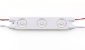
Each pixel in an addressable LED strip consists of three (or four) physical LEDs (red, green, blue, and white) plus a driver IC chip. The chip receives digital data, generates PWM for each channel, and retransmits the signal to the next pixel. The result is a scalable system where each point is completely independent.
Difference between addressable LEDs and standard LEDs
To fully understand the added value of addressable LEDs, it is useful to explicitly compare them with standard LED solutions. A conventional RGB strip has three channels (R, G, B), each of which drives in parallel all LEDs of the same "column" color on the strip: changing red means changing red on the entire strip simultaneously. An addressable LED strip, on the other hand, manages each individual LED (or group of LEDs, called a pixel) completely autonomously: it is possible to have the first pixel blue, the second red, the third yellow, the fourth off, the fifth green… with any gradation, in any combination.
| Characteristic | Standard LED Strip | Addressable LED Strip (Pixel) |
|---|---|---|
| Color Control | All LEDs change together | Each LED/pixel is independent |
| Wiring Complexity | Low (4 wires: V+, R, G, B) | Low (3 wires: V+, GND, DATA) |
| Dynamic Effects | Limited (solid colors, fade) | Unlimited (animations, wave, fire…) |
| Control Chip | None (passive LEDs) | Integrated IC per LED (WS2812B, SK6812…) |
| Control Signal | Analog PWM or 0-10V | Digital (NZR, SPI, PWM) |
| Max LEDs/m | 240 LEDs/m (typical) | 720 LEDs/m (COB pixel) |
| Unit Cost | Lower | Higher (integrated chip) |
| Main Applications | Functional lighting | Effects, art, dynamic signage |
The RGB LED pixel: anatomy, internal structure, and colors
Understanding exactly what an RGB LED pixel is essential for correctly designing any installation with addressable LEDs. In the world of digital lighting, the term pixel has a precise and specific meaning: it is the smallest addressable unit of the system, i.e., the smallest light element that can be controlled individually. What does a pixel correspond to in an LED strip? In most standard pixel LED strips, a pixel coincides with a single SMD LED point (or with a small group of closely spaced LEDs that share the same driver chip). The concept of pixel is therefore borrowed directly from the world of digital displays: just as in a screen each pixel is a colored point that can be controlled autonomously, in a pixel LED strip each light point is a pixel that can assume any color among 16,777,216 possible combinations.
Internal structure of an addressable RGB LED
An addressable LED pixel in the SMD 5050 format (the most widespread, with dimensions 5×5 mm) is internally composed of:
- three emissive LED chips: one red (R, typical wavelength: 620–625 nm), one green (G, 520–525 nm), and one blue (B, 465–470 nm). In RGBW models, a fourth high-CRI white chip is added;
- the driver IC chip: a dedicated microcontroller (for example, the WS2812B circuit) soldered next to the emissive LEDs in the same package. This chip interprets input data, generates PWM for each channel, and manages retransmission to the next pixel;
- a bypass capacitor: typically 100 nF, mounted near the chip to filter current transients during rapid LED switching;
- the substrate and encapsulation: a ceramic or copper base for thermal dissipation and epoxy resin or silicone protection for mechanical robustness.
How many colors can an LED pixel have?
The technical answer is: an RGB LED pixel can display exactly 16,777,216 distinct colors. This number derives from the combination of 256 brightness levels (from 0 to 255) for each of the three color channels, according to the formula 256³ = 16,777,216. In practice, in most applications, human perception cannot distinguish differences below certain step values, so the effective perceived range is "infinite" for any practical lighting and design purpose. With the addition of the white channel (RGBW variant, as in the SK6812), the system adds further flexibility in reproducing whites and pastel tones, significantly improving overall color rendering (CRI).
What are pixel LED strips?
These are addressable LED strips in which the addressing step, i.e., the granularity of control, is at the level of the individual LED or very small groups of LEDs. In some addressable LED strips, multiple LEDs share the same driver chip, forming a segment that behaves as a single pixel: this is the case with some low-density strips where each chip drives 3 or 6 LEDs simultaneously. In high-resolution pixel LED strips, however, the ratio is 1:1, i.e., one chip per LED, ensuring the maximum possible spatial resolution for video animations and art installations.
Pixel resolution in addressable LED strips
An LED strip with 144 LEDs/m at a 1:1 pixel pitch has a resolution of 144 pixels per linear meter, equivalent to the pixel density of a roughly 3.6-inch (91 mm) display with HD resolution. This data is fundamental for calculating animation sharpness as a function of viewing distance: at 2 meters distance, the resolution of 144 LEDs/m is sufficient for smooth and readable animations.
How an RGB LED is made and how it works
As described above, an RGB LED is a package containing three semiconductor junctions of different materials, each emitting a different wavelength of visible light. If you are wondering how an RGB LED works, the answer is simple: when an electric current passes through an LED junction, electrons recombine with holes, releasing energy in the form of photons; the physical phenomenon is called electroluminescence. The frequency (color) of the emitted photons depends on the semiconductor material used: indium gallium nitride (InGaN) for blues and greens, aluminum indium gallium phosphide (AlInGaP) for reds. By combining the three emissions with variable intensity via PWM, any color in the RGB color space can be obtained.
Types of chips for addressable LEDs: WS2812B, SK6812, WS2818, WS2814, and others
The market for addressable LED chips is rich and articulated: each chip responds to specific project needs, with significant differences in terms of supply voltage, communication protocol, number of color channels, PWM frequency, and signal robustness. To make the correct choice, it is essential to know the distinctive characteristics of the main ICs available on the market.
WS2812B: the standard chip for 5V pixel LED strips
The WS2812B is undoubtedly the most well-known and widespread chip in the world of addressable LEDs. Produced by WorldSemi (now Worldsemiconductor), it is the second generation of the WS2812, improved with a more robust internal structure and an updated package (SMD 5050 with separate pads for VDD and VSS, which reduces interference). Its main characteristics are:
- Supply voltage: 5V DC (range: 3.5–5.3V)
- Data protocol: NZR single-wire, speed 800 Kbps
- Bits per pixel: 24 bits (8 bits × G, R, B — note: GRB order!)
- Internal PWM frequency: 400 Hz
- Max current per LED: 60 mA (20 mA per channel × 3)
- Operating temperature: -25°C to +85°C
- Compatibility: maximum, supported by virtually every SPI controller, software library (FastLED, NeoPixel), and control system on the market
Why is it so widespread? Three fundamental reasons: the simplicity of wiring (a single data wire), the availability of documentation and software libraries, and the relatively low cost. The WS2812B is the ideal choice for decorative installations, backlighting, signage, and indoor environments where distances between the data source and the strip are not excessive (max 5–10 meters without signal amplifiers).
SK6812: the RGBW chip for pure whites and high color rendering
The SK6812 from Opsco is the main competitor and complement to the WS2812B. Compatible in terms of protocol (same 800 Kbps NZR standard), it stands out for its availability in an RGBW variant, which adds a fourth white LED channel (W) to the standard RGB package. Its main characteristics:
- Supply voltage: 5V DC (range: 3.7–5.5V)
- Data protocol: NZR single-wire, speed 800 Kbps (WS2812B compatible)
- Bits per pixel (RGBW): 32 bits (8 bits × R, G, B, W)
- Internal PWM frequency: up to 1.1 kHz (higher than WS2812B, reduces flickering)
- Max current per LED (RGBW): 80 mA (20 mA × 4 channels)
- Variants: RGB (24 bits), RGBW (32 bits), RGBNW (neutral white), RGBWW (warm white)
- White CRI: >90 in models with quality white LED
When to choose SK6812 instead of WS2812B? The SK6812 RGBW is the ideal choice when the project requires both dynamic colored effects and high-quality white light, for example in premium residential lighting, showrooms, art galleries, or any space where white color rendering is important. The dedicated white channel produces a significantly purer white than the "synthetic" white obtained by mixing R+G+B at full power, which tends to have a cold and unnatural appearance.
WS2818: signal robustness over long distances
The WS2818 is an advanced chip from WorldSemi that solves one of the main limitations of the WS2812B: the vulnerability of the data signal to interference and chain failures. The WS2818 adopts a dual data wire system (Data + Backup): in case of failure of a single LED, the signal automatically propagates on the backup wire, allowing the chain to continue functioning without interruptions. This makes it ideal for critical installations where reliability is fundamental (safety lighting, signage, permanent installations). It also supports 12V or 24V voltages in specific versions, improving long-run management.
WS2814: 24V RGBW for professional installations
The WS2814 is the 24V four-channel RGBW version of the WS2812 family. The higher operating voltage (24V instead of 5V) drastically reduces circulating current and therefore Joule effect losses, allowing much longer strips to be powered without voltage drop problems. It is the professional choice for large-scale architectural installations with high color quality requirements. Products like the F52-CoR400-784OR2 integrate this chip, offering 24V RGBW pixel control with CRI>90.
APA102 and SK9822: the high-speed two-wire SPI variant
For high-speed update applications, such as LED walls for high-frequency video, installations with effects synchronized to real-time audio, or POV (Persistence of Vision) projects, the APA102 chip and its equivalent SK9822 offer an interesting alternative. Unlike NZR chips, these use a two-wire SPI protocol (Clock + Data) that allows much higher update frequencies (up to 20 MHz) and more precise synchronization between pixels. However, they require a controller with dedicated SPI output (clock + data), unlike the single data wire of the WS2812B.
| Chip | Voltage | Channels | Protocol | Bits/Pixel | PWM Hz | Main Use Case |
|---|---|---|---|---|---|---|
| WS2812B | 5V | RGB | NZR 800Kbps | 24 bit | 400 Hz | Standard maker/decorative |
| SK6812 RGB | 5V | RGB | NZR 800Kbps | 24 bit | 1.1 kHz | Less flickering, WS2812B replacement |
| SK6812 RGBW | 5V | RGBW | NZR 800Kbps | 32 bit | 1.1 kHz | Pure white + colors, high CRI |
| WS2814 | 24V | RGBW | NZR 800Kbps | 32 bit | 2 kHz | Long installations, high quality |
| WS2818 | 12/24V | RGB | NZR + backup | 24 bit | 2 kHz | Robustness, fault tolerance |
| APA102 | 5V | RGB | SPI 2-wire | 32 bit | ~19.2 kHz | High speed, POV, LED video |
| WS2801 | 5V | RGB | SPI 2-wire | 24 bit | Var. | Medium speed, good compatibility |
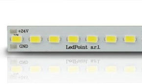
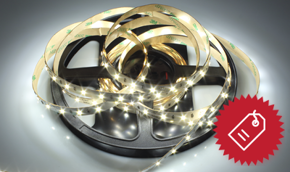
Addressable pixel LED strips: characteristics, density, and product types
Addressable pixel LED strips, also called addressable LED strips or simply digital LED strips, are the flagship product of modern advanced lighting. Understanding their main technical characteristics is a prerequisite for making correct purchasing decisions and for designing systems that meet requirements for brightness, aesthetic effect, durability, and cost. In this section, we analyze the fundamental variables that distinguish one pixel LED strip from another.
LED density: the key variable for effect quality
The LED density in an addressable LED strip is expressed in LEDs per meter (LED/m) and directly determines visual resolution, animation fluidity, and the ability to eliminate the dotted effect at close range. How much do LEDs illuminate? Total brightness is proportional to the number of LEDs and the luminous flux of each LED, typically expressed in lumens per meter (lm/m). A 60 LED/m WS2812B strip delivers approximately 800–1000 lm/m at full white power; a 144 LED/m strip can reach 2500 lm/m; the COB version at 720 LED/m can exceed 5000 lm/m.
- 30–60 LED/m: low density, suitable for perimeter lighting at medium viewing distance (>1 m), furniture backlighting, frames;
- 96–144 LED/m: high density, suitable for video effects, detailed animations, architectural mapping at short distance;
- 240–576 LED/m: high density, for COB pixels with continuous effect, close-range accent lighting;
- 720 LED/m: COB pixel maximum density (e.g., WS2818), for perfectly fluid effects without any visible granularity even at close range.
Supply voltage: 5V vs 12V vs 24V
The supply voltage has a direct impact on system management, especially for long-run installations. Addressable LED strips at 5V (like those with standard WS2812B) are subject to significant voltage drops on runs longer than 1–2 meters, requiring frequent power injections. Strips at 24V (like those with WS2818 or WS2814) allow significantly longer runs, up to 10–15 meters per injection, reducing the number of power points and simplifying wiring for large installations.
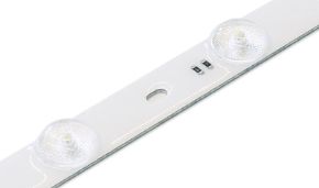
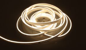
COB pixel strips: the evolution for a continuous effect without dots
COB Pixel (Chip-On-Board Pixel) technology represents the most recent evolution in the world of addressable pixel LED strips. In a COB strip, the LEDs are not discrete separate SMD packages with empty spaces between them, but a matrix of micro LED chips deposited directly on the PCB substrate, covered by a continuous phosphor layer. The visual result is a perfectly uniform and continuous line of light, free of the "dotted" effect typical of traditional strips, even when viewed up close. This characteristic makes it particularly appreciated for:
- accent lighting in niches, false ceilings, and visible architectural profiles;
- museum installations and art galleries where aesthetics are a priority;
- high-end interior design solutions;
- backlighting of panels and signage where absolute uniformity is required.
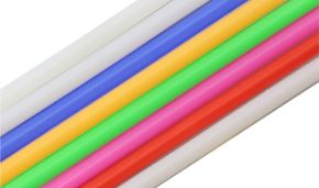
IP protection rating: LED strips for indoor and outdoor environments
The IP (Ingress Protection) classification of addressable LED strips determines their suitability for different installation environments
| IP Rating | Protection | Recommended Application |
|---|---|---|
| IP20 | Only large dust | Dry indoor environments (false ceilings, furniture) |
| IP44 | Water splashes | Bathrooms (not shower), semi-protected environments |
| IP65 | Directional water jet | Protected outdoors, pool edges, garden lighting |
| IP67 | Temporary immersion (30 min, 1 m) | Tanks, fountains, exposed outdoor installations |
| IP68 | Prolonged immersion | Pools, aquariums, underwater environments |
The SPI controller for addressable LEDs: what it is, how it works, and how to use it
The SPI controller, where SPI stands for Serial Peripheral Interface, is the brain of the lighting system with addressable LEDs. Without a controller, pixel LEDs are simple passive components incapable of expressing their potential: it is the controller that translates the user's intention (a color, an effect, an animation) into digital signals that WS2812B, SK6812, or other IC chips can interpret and execute. Understanding in depth what an SPI controller is, how it works, and how it integrates into the system is the foundation of any professional project with addressable pixel LED strips.
What is the SPI controller for addressable LEDs
Technically, the term SPI controller for LEDs in the context of addressable LED strips refers to a specialized hardware device that:
- receives commands from the user via an interface (smartphone app, RF remote, DMX console, UDP/Artnet signal from the local network or Internet);
- generates data packets in the correct format for the LED chip mounted on the strip (e.g., NZR format for WS2812B, with bits in GRB order);
- sends the signal on the strip's data line at a cyclic rate (typically 30–100 times per second) to update colors and animations in real time;
- manages internal effects and animations, allowing complex patterns to be executed without the controller having to receive every single update from the outside.
The term SPI in the commercial name of controllers for addressable LEDs is often used loosely, to indicate controllers that can manage chips with SPI interface (like APA102) but also, and above all, chips with NZR interface (like WS2812B and SK6812). In practice, when talking about programming with SPI controllers for addressable LED strips, it means using a dedicated hardware controller that generates the digital signals necessary to drive the pixels.
How to use the SPI controller
The process of using an SPI controller for addressable LED strips is articulated in four main phases:
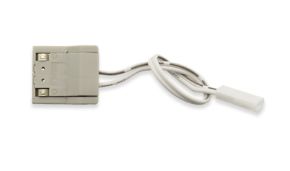
Phase 1 — Physical connection
The controller must be connected to the LED strip via at least three connections:
- DATA (DIN): the digital signal wire that carries commands to the pixels;
- GND: the common ground shared between controller, power supply, and strip;
- V+ (optional): some controllers provide power to the strip, others do not — in that case the strip is powered directly from the power supply, with the controller controlling only the data signal.
Phase 2 — Chip type configuration
The controller must know which chip is mounted on the strip to generate signals in the correct format. Each chip has slightly different bit timings (e.g., the WS2812B requires a "1" with 0.8µs high / 0.45µs low, while a "0" is 0.4µs high / 0.85µs low). In Skydance controllers, this configuration is done by setting the IC Type code via the R9 remote or the Tuya app.
Phase 3 — Defining the number of pixels
The controller must know the exact number of pixels in the chain to generate data packets of the correct length. If the configured number is less than the actual number, the excess pixels will always remain at the previous color; if it is greater, the controller will send data to non-existent pixels, causing erratic behavior.
Phase 4 — Programming effects and animations
Once correctly configured, the controller allows selection among available operating modes: static color, transitions, preset dynamic effects (wave, fire, rainbow, scanner, strobe, etc.) or advanced programming mode via app or external software.
Communication protocols to the controller
Modern SPI controllers for addressable LEDs support different protocols for receiving commands from the outside, each suited to specific use scenarios
| Protocol | Description | Typical Use Case |
|---|---|---|
| RF (Radio Frequency) | Wireless radio remote, range ~10–20 m | Home use, simple, no Wi-Fi |
| Wi-Fi (Tuya/SmartLife) | Connection to Wi-Fi network, app control | Smart home, automation, remote control |
| DMX512 | Professional standard for stage lighting | Theater, events, concerts, nightclubs |
| Artnet/sACN | DMX over Ethernet/UDP network | Large installations, LED walls, mapping |
| PWM | Analog signal 0–100% duty cycle | Simple dimming, integration with KNX systems |
| MIDI | Musical protocol for synchronization | Synchronization with musical instruments |
| USB/Serial | Direct connection to PC/Raspberry Pi | Prototyping, interactive installations |
How to program WS2812B LED strips: complete operational guide
Programming WS2812B LED strips is one of the most searched and discussed topics in the field of pixel lighting. Whether using a microcontroller like Arduino or Raspberry Pi, or preferring a dedicated hardware controller like those in the Skydance series, the fundamental principles remain the same. In this section, we analyze both approaches with operational detail, providing step-by-step instructions to achieve professional results.
The NZR protocol of the WS2812B: timings and packet structure
Before being able to program WS2812B correctly, it is essential to understand the communication protocol that the chip uses to interpret data. The WS2812B uses a proprietary NZR (Non-Return-to-Zero) protocol, transmitted on a single data wire. The distinction between bit "1" and bit "0" occurs through pulse duration:
- Bit "1": HIGH pulse of ~0.8µs, followed by LOW pulse of ~0.45µs (total time ~1.25µs ± 600ns)
- Bit "0": HIGH pulse of ~0.4µs, followed by LOW pulse of ~0.85µs (total time ~1.25µs ± 600ns)
- Reset: LOW signal for at least 50µs (in version B, reduced from 280µs of the original WS2812 version)
Data packet structure for WS2812B: each LED consumes 24 bits in the order G[7:0] R[7:0] B[7:0] (note: the order is GRB, not RGB!). The most significant bit (MSB) of each byte is transmitted first. For a strip of N LEDs, the total data packet is N × 24 bits, sent in sequence on the DATA wire. After the last bit of the last LED, the reset signal concludes the transmission and all LEDs simultaneously update their colors to the received value.
Programming WS2812B with Skydance WT-SPI hardware controller
For most professional and semi-professional applications, the most practical approach to program WS2812B without having to write code is to use a dedicated hardware controller. The WT-SPI controller from Skydance is the most versatile and powerful solution for this purpose.
Step-by-step procedure to program WS2812B with WT-SPI
- Physical connection: connect the controller's DATA OUT terminal to the strip's DIN terminal. Connect the controller's GND to the common GND of the power supply and strip. If necessary, also connect the power supply's V+ terminal to the strip. Note: do not power the strip through the controller for strips with more than 30 LEDs; always use a separately sized power supply.
- Power on and Wi-Fi connection: power on the controller. In the first configuration, the controller enters Access Point mode. Download the Tuya Smart or SmartLife app on your smartphone and follow the pairing procedure to connect the controller to your home or venue Wi-Fi network.
- Setting IC Type: in the app, access the device's advanced settings. Select the type of IC mounted on the strip. For WS2812B, select code C12 (WS2811/WS2812). This step is fundamental: if the IC Type is incorrect, colors will be distorted or the system will not work.
- Configuring color order (Color Order): WS2812B uses GRB (green-red-blue) order, not RGB. In the app, set the order to GRB. Otherwise, when you select red the LED will show green, and vice versa.
- Setting number of pixels (Pixel Length): enter the exact number of LEDs in the connected strip. For a 1-meter strip at 144 LED/m, enter 144. For 2 meters of the same strip, enter 288.
- Functionality test: select white color (R=255, G=255, B=255) and verify that all LEDs turn on correctly. Then test red and green to verify that the color order is correct.
- Creating effects and scenes: via the Tuya app it is possible to create custom scenes, program timers, activate preset effects (rainbow, scrolling, pulsing, fire, etc.) and define independent segments of the strip with different colors and effects.
Programming WS2812B with Arduino and FastLED library
For those who want maximum creative control over LED behavior, programming via Arduino (or any compatible microcontroller) with the FastLED library is the most powerful approach. FastLED is the most advanced and optimized open source library for controlling addressable LEDs on Arduino, ESP8266, ESP32, Teensy, and many other platforms.
Basic code example for WS2812B with FastLED
#include <FastLED.h>

#define NUM_LEDS    144     // Number of LEDs in the strip
#define DATA_PIN    6       // Arduino pin connected to strip DIN
#define LED_TYPE    WS2812B
#define COLOR_ORDER GRB     // WS2812B color order

CRGB leds[NUM_LEDS];

void setup() {
  // FastLED initialization
  FastLED.addLeds<LED_TYPE, DATA_PIN, COLOR_ORDER>(leds, NUM_LEDS)
         .setCorrection(TypicalLEDStrip);
  FastLED.setBrightness(80); // Global brightness (0-255)
}

void loop() {
  // Scrolling rainbow effect
  static uint8_t hue = 0;
  for(int i = 0; i < NUM_LEDS; i++) {
    leds[i] = CHSV(hue + (i * 10), 255, 255);
  }
  FastLED.show();
  delay(20);
  hue++;
}
FastLED offers an extraordinarily rich set of functions for creating complex effects: fade, blend, color palettes, physical simulations (fire, water, plasma), synchronization with audio signals via sensors, management of 2D matrices, and much more. The library is extensively documented and supported by a very active global community.
Programming WS2812B with Adafruit NeoPixel
The Adafruit NeoPixel library is the simpler alternative to FastLED, with a more direct but less optimized API. It is the ideal choice for educational projects, rapid prototypes, and situations where code simplicity is a priority over performance. Both libraries are available for free via the Arduino IDE Library Manager and are fully compatible with WS2812B.
How to program SK6812 LED strips: configuration and advanced specifications
Programming SK6812 LED strips follows principles similar to WS2812B programming — the communication protocols are compatible — but requires some additional attention related to managing the fourth white channel (in RGBW models) and the chip's slightly different specific timings. In this section, we delve into everything you need to know to program SK6812 with SPI controllers or microcontrollers, getting the most out of its RGBW technology.
SK6812 vs WS2812B protocol: similarities and differences
The SK6812 chip uses an NZR protocol similar but not identical to WS2812B
- Transfer speed: 800 Kbps (identical to WS2812B)
- Bits per pixel (RGB): 24 bits (G[7:0] R[7:0] B[7:0]), like WS2812B
- Bits per pixel (RGBW): 32 bits (G[7:0] R[7:0] B[7:0] W[7:0]), adds the white channel
- Reset time: ≥80µs (vs ≥50µs for WS2812B), important in microcontroller implementations
- Default color order: GRB for the RGB variant, GRBW for the RGBW variant.
Programming SK6812 with WT-SPI controller: IC Type setting
To program SK6812 via the Skydance WT-SPI controller, the procedure is similar to that for WS2812B, with the main difference in the IC Type setting:
- for SK6812 RGB: select the code corresponding to SK6812 RGB in the app menu (always check the controller manual for the exact code for your firmware);
- for SK6812 RGBW: select code C18 in the Skydance controller's IC Type menu, which specifically corresponds to SK6812 RGBW and correctly handles the 32 bits per pixel including the white channel.
SK6812 RGBW: the control software must be compatible with managing 4 channels per pixel. In a system that only manages 3 channels (RGB), the fourth W channel of the SK6812 RGBW will always be kept at zero, nullifying the chip's main advantage. Always verify that your controller and software explicitly support RGBW mode before purchasing.
Programming SK6812 RGBW with FastLED: managing the white channel
In the FastLED library, support for SK6812 RGBW requires some specific considerations. Since FastLED internally manages colors in 3-channel RGB format, to leverage the white channel of the SK6812 RGBW you need to use the CRGBW structure or resort to alternative libraries like Adafruit NeoPixel (which natively supports RGBW with the NEO_GRBW parameter) or the NeoPixelBus library, specifically designed to also handle RGBW pixels with maximum efficiency and quality.
// Example with NeoPixelBus library for SK6812 RGBW
#include <NeoPixelBus.h>

const uint16_t PixelCount = 60;
const uint8_t PixelPin = 6;

// Definition for SK6812 RGBW
NeoPixelBus<NeoGrbwFeature, Neo800KbpsMethod> strip(PixelCount, PixelPin);

void setup() {
  strip.Begin();
  strip.Show();
}

void loop() {
  // Set first LED to pure white (only W channel)
  strip.SetPixelColor(0, RgbwColor(0, 0, 0, 255));

  // Set second LED to red (only R channel)
  strip.SetPixelColor(1, RgbwColor(255, 0, 0, 0));

  // Set third LED to warm white (mix RGB + W)
  strip.SetPixelColor(2, RgbwColor(50, 30, 0, 200));

  strip.Show();
  delay(1000);
}
The Skydance SPI ecosystem: WiFi controllers, DMX, and staircase automation
Integrating pixel technology into lighting design represents the most advanced level of lighting control, allowing each single point (or segment) of the strip to be managed independently via the SPI signal. To realize dynamic projects with widespread chips like the WS2812B or SK6812, Skydance offers a complete ecosystem of professional sources and control units that covers every need, from smart home control to professional theatrical installations. In this section, we analyze in detail the three main families of available controllers.
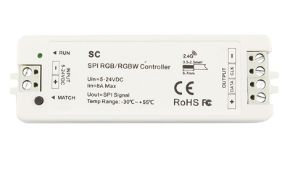
WiFi & RF WT-SPI Series Controllers: the Smart solution for residential and commercial use
The WT-SPI controller from Skydance is the most versatile and accessible solution in the ecosystem for programming with SPI controllers in Smart Home and medium-complexity commercial installations. Its main characteristics make it suitable for a wide variety of application scenarios.
Main technical characteristics of the WT-SPI
- Chip compatibility: supports 49 different LED IC types, including WS2812B, SK6812, WS2818, WS2814, APA102, TM1814, and many others
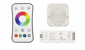
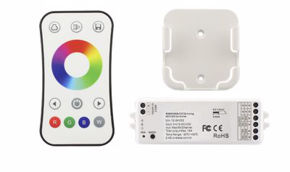
- Connectivity: Wi-Fi 2.4 GHz + RF 433 MHz (R9 remote included)
- Compatible app: Tuya Smart / SmartLife — available for iOS and Android, compatible with Google Home and Amazon Alexa
- Max manageable pixels: up to 1000 pixels per output
- Input voltage: 5–24V DC (depending on model)
- Preset effects: over 180 dynamic effects included in firmware
- Advanced functions: definition of independent segments, pixel-by-pixel light painting, programmable timers, multiple scenes
Advanced configuration via Tuya app: one of the most powerful functions of the WT-SPI is the ability to divide the LED strip into independent segments, each controllable with its own color, effect, and timing. For example, on a 200-pixel strip it is possible to configure the first 50 as fixed red accent, the next 100 as animated moving sequence, and the last 50 as stable white, all managed by a single controller. Via the app it is also possible to achieve light painting: pixels are selected individually and each is assigned a specific color, creating custom graphic patterns.
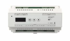
DMX-SPI DS Series Controllers: professional control for events and scenography
For professional applications in nightclubs, theaters, television studios, concert halls, and large-scale events, the reference protocol is DMX512, the industrial standard that guarantees reliability, low latency, and universal compatibility with all professional lighting consoles on the market. The DS and DS-L series decoders from Skydance solve the interface problem between DMX systems and pixel LED strips, converting the DMX signal into SPI output compatible with WS2812B and SK6812.
How the DS series DMX-SPI decoder works
- The DMX console (grandMA, Avolites, ETC Ion, etc.) sends the DMX512 frame via 5-pin XLR cable (or 3-pin XLR with adapter)
- The DS decoder receives the DMX frame and decodes it, identifying the channels assigned to the pixel output
- The decoder generates the appropriate SPI/NZR signal for the configured chip type and sends it to the LED strip
- The pixels update in real time at the DMX refresh frequency (typically 40 Hz)
Advanced capabilities of the DS/DS-L
- Support for 32 internal dynamic modes (standalone, without DMX console)
- Flexible mapping of DMX channels to pixels: 1 channel per pixel (white), 3 channels per pixel (RGB), 4 channels per pixel (RGBW)
- Concatenation of decoders to manage very long strips with a single DMX chain
- DMX addresses configurable via DIP switch or digital interface
- Compatibility with RDM (Remote Device Management) mode for bidirectional configuration from console
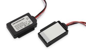
ES-D(WT) staircase controllers: automation of luminous pathways
The ES-D(WT) controller is a specialized product for one of the most appreciated applications of addressable LEDs in residential and contract settings: staircase lighting with staircase/cascade effect. This controller uses PIR sensors (passive infrared) to detect the movement of a person approaching the stairs, automatically activating the characteristic "cascade" or "scrolling" effect of pixel LEDs, with steps lighting up progressively one after another in the direction of travel, creating a sophisticated visual effect that is also functional at the same time.
Characteristics of the ES-D(WT) controller
- Integratable PIR sensors: up to 2 presence sensors (one for each end of the stairs)
- Manageable pixels: up to 960 total pixels
- Effect modes: flow cascade (classic scrolling), breathing, rainbow, fixed color — all configurable
- Wi-Fi connectivity: integration with Tuya app for customization of colors, effect speed, brightness, night timer
- Light sensor: automatic activation only when the environment is dark (integratable photoresistor)
- Automatic timeout: the stairs automatically turn off after a configurable time from the last movement detection
Technical configuration guide: IC type, RGB order, and pixel length
The precise configuration of an SPI controller for addressable LED strips is the critical point that determines whether the system will work correctly or whether the LEDs will show wrong colors, disturbed effects, or unpredictable behavior. This section is a detailed technical guide to the three fundamental parameters that every installer must configure with precision: the IC type, the RGB color order, and the number of pixels.
Selecting the IC type (IC Type)
The IC Type parameter tells the controller which LED chip is mounted on the strip, so that it can generate signals with the exact bit timings required by that specific chip. Setting the wrong IC Type is the most common cause of malfunctions in new installations.
In Skydance controllers, the IC Type code is set via the R9 remote (by pressing the IC button and then the code numbers) or via the Tuya app in the advanced settings section. The main codes for the most common chips are:
| IC Code | Compatible Chips | Bits/pixel | Note |
|---|---|---|---|
| C12 | WS2811, WS2812, WS2812B | 24 bit (RGB) | Most common standard |
| C18 | SK6812 RGBW | 32 bit (RGBW) | Manages white channel |
| C19 | SK6812 RGB | 24 bit (RGB) | Like C12 but with SK6812 timing |
| C24 | WS2818 | 24 bit (RGB) | Dual-wire protocol |
| C30 | WS2814 RGBW | 32 bit (RGBW) | 24V RGBW |
| C01 | WS2801 | 24 bit (RGB) | 2-wire SPI interface |
| C05 | APA102, SK9822 | 32 bit (RGB+br.) | SPI clock+data |
How to identify your strip's chip? If you don't know which chip is mounted on the strip, look for the code printed on the LED package (visible with a magnifying glass) or in the product's technical documentation. On the Ledpoint.it catalog, each strip clearly indicates the chip type in the commercial name and in the technical sheet.
RGB color order (Color Order)
Each LED chip manufacturer may have chosen a different order for the bytes of the three color channels in the data packet. Despite RGB seeming like the obvious standard, many chips, including the very popular WS2812B, use a different order. If the controller sends data in the wrong order, colors will be inverted (for example, selecting red will give green).
The six possible color orders are: RGB, RBG, GRB, GBR, BRG, BGR. Skydance controllers allow selection among all six. The most common cases:
- GRB: WS2812B, WS2812, SK6812 RGB. Note! Despite being called "RGB" in the name, the WS2812B chip uses GRB as data order
- RGB: WS2801, APA102, TM1804
- GRBW: SK6812 RGBW (in 4-channel systems)
- BRG: some less common chips from minor Asian manufacturers
Pixel Length (number of pixels)
The Pixel Length parameter defines how many pixels (LEDs or groups of LEDs) are connected to the controller output. Setting this value correctly is essential for the correct propagation of dynamic effects along the entire strip.
Calculating the number of pixels
- Standard strip (1 LED = 1 pixel): Pixel Length = Length in meters × LED density/m. Example: 2 meters of strip at 144 LED/m = 288 pixels.
- Strip with groups of LEDs per pixel: check the product's technical sheet. Some low-density strips have 3 or 6 LEDs for each IC chip; in that case, the number of pixels is one-third or one-sixth of the total number of LEDs.
- Multiple strips in cascade: if multiple strips are connected in series on the same output, the Pixel Length must be the total sum of pixels from all strips.
Powering addressable LED strips: calculations, voltage drop, and safety
Correctly sizing the power supply is one of the most critical, and most often overlooked, aspects in installations with addressable LEDs. An undersized power supply not only causes malfunctions and flickering, but can damage components and create safety risks. For high-density pixel strips, especially at 5V, it is essential to correctly size the power supply (at least 1.2 times the nominal load) and provide power injections every 2–5 meters to avoid brightness drops or color shifts.
How to calculate the consumption of an addressable LED strip
The total consumption of an addressable LED strip depends on the number of LEDs, the type of chip, and the maximum current per channel. The conservative calculation starts from the theoretical maximum power (all LEDs at full white, all channels at maximum), reduced by a practical factor based on typical use.
Formula:
Total Power (W) = N_LED × Current_per_LED (A) × Voltage (V)
For a WS2812B at full white power: 60 mA per LED × 5V = 0.3W per LED.
| Strip (density) | LED/m | Max current/LED | Max consumption/m | Typical consumption/m (30%) |
|---|---|---|---|---|
| WS2812B 60 LED/m | 60 | 60 mA | 18W/m | ~5.4W/m |
| WS2812B 144 LED/m | 144 | 60 mA | 43.2W/m | ~13W/m |
| SK6812 RGBW 60 LED/m | 60 | 80 mA | 24W/m | ~7.2W/m |
| WS2818 COB 720 LED/m | 720 | ~15 mA | ~54W/m | ~16W/m |
| WS2814 RGBW 24V 96 LED/m | 96 | 60 mA | 138W/m | ~41W/m |
Voltage drop: the main problem with 5V strips
Voltage drop is the physical phenomenon whereby the voltage available to the LEDs progressively reduces as you move away from the power point, due to the resistance of the copper conductors on the strip's PCB. For 5V strips this effect is particularly pronounced due to the high current: on a WS2812B strip at 144 LED/m powered only at the beginning, the voltage drop along the linear meter can reach 0.5–1V, causing a progressive "shift" in color and reduction in brightness toward the end of the strip.
Solution: multiple power injection
The practical rule for 5V addressable LED strips is: inject power every 1–2 meters for density ≥144 LED/m, or every 2–5 meters for density 30–60 LED/m. For 24V strips (like those with WS2814 or WS2818 at 24V), it is possible to power runs of 5–15 meters from a single point, significantly reducing wiring complexity.
Golden rule for power supply sizing: calculate the maximum theoretical power of the strip (all LEDs at full white) and multiply by 1.2–1.5. For example, for 5 meters of WS2812B 60 LED/m: 5m × 18W/m × 1.2 = 108W → choose a power supply of at least 120W at 5V. Always use power supplies with CE certification and integrated protections (overcurrent, overvoltage, short circuit).
Electrical safety in installations with addressable LED strips
Safety is a non-negotiable aspect in installations with addressable LED strips. Here are the fundamental rules to follow:
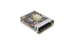
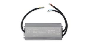
- Certified power supplies: use only power supplies with CE marking, UL certification or similar, and integrated protections against overcurrent, overvoltage, and short circuit;
- Adequately sized cables: for power injections on 5V strips with high currents, use cables of at least 2.5 mm² for runs longer than 1 meter, and 4 mm² for longer runs;
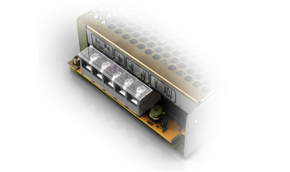
- Protection fuses: insert a fuse on the positive at each power injection point;
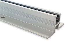
- Thermal dissipation: mount strips on aluminum profiles to distribute heat and protect both the LED and the adhesive;
- Bypass capacitors: add a 1000 µF electrolytic capacitor / correct voltage (e.g., 10V for 5V strips, 35V for 24V strips) between V+ and GND at each injection point to dampen transients.
Applications of addressable LEDs: professional and creative scenarios
The catalog of practical applications for addressable LEDs is practically unlimited: any context where programmable, dynamic, and customizable light is desirable is potentially an opportunity for pixel LED strips. In this section, we explore in detail the most relevant application scenarios for professionals (interior architects, lighting designers, event organizers, electrical technicians, and marketing managers), providing concrete examples, specific technical indications, and references to the most suitable Ledpoint products.
Architecture and interior design: programmable lighting for modern spaces
In contemporary interior design, lighting is no longer an accessory element but a primary design component. Addressable pixel LED strips open extraordinary possibilities for architects and interior designers: animated luminous ceilings, dynamic light walls, illuminated handrails with staircase effects, backlighting of cladding panels with depth and movement effects. The progressive ignition LED strip, where LEDs activate sequentially from beginning to end, is one of the most appreciated effects for stairs, corridors, and transition environments.
Practical case — Dynamic accent wall in a lounge
A COB Pixel strip at 720 LED/m mounted in a vertical architectural profile and controlled via WT-SPI with programmed scenes can create an extremely realistic effect of flowing water or chromatic mist, immediately capturing attention and becoming a scenographic element of great impact without requiring maintenance.
Lighting for events, concerts, and nightclubs
In the professional events sector, addressable LEDs have revolutionized the way stage, corridor, backdrop, and environmental lighting is designed. Synchronization with music, possible via audio analyzers connected to SPI controllers, allows the creation of real-time light choreographies that blend perfectly with the sound performance. Skydance's DS series DMX-SPI decoders, integrated with standard lighting consoles in the live events sector (grandMA, Hog 4, ETC Eos), allow professional lighting designers to control thousands of pixels with the same precision and fluidity as a traditional LED bar, but with infinitely greater creative freedom.
Dynamic signage and visual merchandising
For retail and visual marketing, pixel LED strips offer unique differentiation possibilities. Luminous signage with lettering made with addressable LED strips can alternate brand colors, create scrolling or pulsing text animations, and respond in real time to promotional campaigns via remote update. All without the complexity of a traditional LED display.
Artistic installations and digital art
Addressable pixel LED strips have become a fundamental tool for interactive digital art. Installations like "reactive light walls" that respond to visitor movement, animated luminous sculptures, light tunnels with projections of mathematical patterns, or works that visualize real-time data such as air temperature or social media traffic volume — all these creations leverage the capabilities of pixel LEDs managed by microcontrollers like Arduino, Raspberry Pi, or dedicated platforms like Resolume or MadMapper.
Gaming environments, home theater, and bias lighting
The widespread consumer use is bias lighting for monitors and TVs: addressable LED strips mounted on the back of a display and programmed to mirror the colors of the screen edge ("Ambilight" function in Philips TVs, but replicable with open source systems like Hyperion or Prismatik with WS2812B strips). In gaming and home theater setups, pixel LED strips create reactive light environments that amplify the immersive experience.
Addressable circadian lighting: dynamic white for offices and hospitals
An emerging application of great interest for the healthcare, education, and high-productivity office sectors is addressable circadian lighting: the ability to automatically vary the light color temperature (from warm white 2700K to cold white 6500K) throughout the day, following the natural rhythm of the sun to support the biological rhythm of occupants. The F52-CoCCT-120812 strip allows management of dynamic white (CCT) in segments via SPI controller, opening professional scenarios of great interest for the healthcare and corporate markets.
Dimmable LEDs and addressable LEDs: differences and integration
A very common doubt among those approaching the world of addressable LEDs concerns the difference between dimmable LEDs and addressable LEDs, and the possibility of integrating the two technologies. Clarifying this distinction is useful for making informed project decisions and for understanding when one technology is preferable to the other.
What does dimmable LED mean?
A dimmable LED is an LED (or an LED strip) whose brightness can be continuously regulated between maximum and minimum, typically via a PWM (Pulse Width Modulation) signal, 0–10V, DALI, or TRIAC/ELV for mains systems. Dimming is a characteristic of brightness control, not color. A standard dimmable LED (non-addressable, non-RGB) can only vary its light intensity while keeping the emitted light color fixed.
How to make an LED dimmable
To make any LED strip dimmable, it is sufficient to interpose a dimmer compatible with the strip's technology between the power supply and the strip
- for single-color strips at 12V/24V: a PWM dimmer (typical range 0–100%, frequency 1–20 kHz) connected between power supply and strip;
- for RGB strips at 12V/24V: an RGB dimmer (3 independent PWM channels) or an RGB controller;
- for 220V LED strips: a TRIAC or Leading/Trailing Edge dimmer (always ensure compatibility declared by the manufacturer);
- for professional systems: DALI (Digital Addressable Lighting Interface) modules for integration with building management systems (BMS).
Are addressable LEDs dimmable?
The answer is yes, addressable LEDs are intrinsically dimmable, and in a much more powerful way than any external dimming solution. Since each LED chip incorporates a digitally programmable 8-bit PWM generator (256 levels), the brightness of each pixel can be set individually with precision to any value between 0 and 100%. This means that with an addressable LED system it is possible to do both global dimming (reduce the brightness of all LEDs in the same way) and differentiated dimming (each pixel at a different brightness), creating luminous gradients and shades impossible with traditional dimmer systems.
Software and libraries for programming with SPI controllers: FastLED, Adafruit NeoPixel, Tuya
Choosing the right software is crucial to fully exploit the potential of addressable LEDs. The software ecosystem for controlling pixel LEDs is extraordinarily rich, with solutions ranging from open source libraries for Arduino to consumer smartphone apps, to professional VJ/media server software for art installations and scenography. In this section, we analyze in detail the main available options, with practical indications for each use scenario.
FastLED: the definitive library for addressable LEDs on microcontroller
FastLED is the most complete, performant, and widespread open source library for controlling addressable LEDs on microcontroller platforms. Actively developed and maintained on GitHub, it supports dozens of LED chips (WS2812B, SK6812, APA102, WS2801, TM1803, and many others) and a wide range of hardware platforms (Arduino Uno/Mega/Nano/Pro Mini, ESP8266, ESP32, Teensy, SAMD, STM32, etc.).
Main features of FastLED
- High-level API for managing pixel arrays (CRGB, CHSV, CRGBPalette16)
- Optimized mathematical functions for LEDs (sin8, cos8, scale8, lerp8by8)
- Library of predefined and customizable color palettes (RainbowColors_p, CloudColors_p, ForestColors_p, etc.)
- Physical simulation functions (Fire2012, plasma, "Larson scanner")
- Support for 2D matrices (XYserpentine, XYmatrix)
- Gamma correction and color correction for color temperature
- Automatic frame rate throttling to avoid data bus overload
- Multiple output management (multiple strips on different pins, or multiple strips in parallel)
Adafruit NeoPixel: simplicity and accessibility for first projects
The Adafruit NeoPixel library is the ideal choice for those approaching addressable LED programming with Arduino for the first time. With an extremely simple API and excellent documentation (Adafruit Learning System), it allows creating first effects in minutes. It supports WS2812B, SK6812, WS2812, WS2811, and RGBW variants.
Tuya Smart / SmartLife app: code-free control for professional use
The Tuya Smart app (and its twin SmartLife) is the smart home control platform used by Skydance controllers distributed by Ledpoint.it. For many installers and professionals, this app represents the most practical solution for controlling addressable LEDs without having to write a single line of code:
- intuitive graphical interface for selecting colors and animations;
- "segment control" function to manage independent zones on the same strip;
- programming of scenes and daily/weekly timers;
- integration with Amazon Alexa and Google Assistant for voice control;
- support for conditional automations (e.g., "turn the strip red when a notification arrives");
- compatibility with the Tuya ecosystem (sensors, switches, etc.) for IoT installations;
- remote access via Tuya cloud even outside the local network.
Professional software: MadMapper, Resolume, xLights
For the most advanced installations (LED walls, large-scale architectural mapping, synchronization with real-time video) professionals resort to dedicated software:
- MadMapper: video mapping software for Mac/PC, supports Artnet/sACN output for addressable LEDs and allows mapping video and generative content onto any LED surface;
- Resolume Avenue/Arena: professional VJ software with native support for LED strips via DVI-to-SPI or Artnet output, used in nightclubs and concerts worldwide;
- xLights: open source software specialized in LED sequencing for Christmas decorations and large animated displays; supports Artnet and E1.31 sACN;
- Jinx!: freeware LED matrix controller software, excellent for LED displays with matrices of addressable strips;
- Hyperion NG: for TV and monitor bias lighting, captures screen colors and projects them onto the WS2812B strip connected via USB or network.
Practical installation of an addressable LED strip: tools, connections, and configuration
Moving from theory to practice is the most delicate moment in working with addressable LED strips. A poorly executed installation, even with the most expensive components, will produce disappointing results, operational problems, and potential safety risks. In this section, we provide a complete operational guide for the professional installation of an addressable LED strip, from tool selection to final testing.
Tools needed for installation
- Precision screwdrivers (for controller and power supply terminal blocks)
- Utility knife or sharp scissors for cutting the strip at designated cut points (marked with a line and scissors symbol every group of LEDs)
- Soldering iron + good quality solder (for permanent PCB connections)
- Quick connectors for LED strips (clip-on, solderless, for testing and less critical installations)
- Digital multimeter for voltage, continuity, and current verification
- Desoldering pump or wick in case of soldering errors
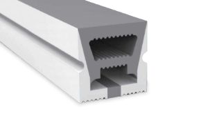
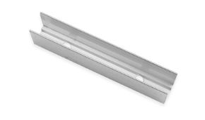
- Aluminum profiles with diffuser cover (opal or transparent) for final mounting
- Neutral silicone for sealing profile ends in humid environments
- Labeler for marking cables (mandatory in installations with multiple strips)
Step-by-step procedure: installing a pixel LED strip with WT-SPI controller
Step 1 — Preliminary planning and calculations
Before purchasing any components, define: total strip length, chosen chip type, supply voltage, number of required injection points, controller type (Wi-Fi, DMX, staircase), application, and desired effects. Based on this data, calculate total consumption and size the power supply.
Step 2 — Preparing the support
Clean with isopropyl alcohol the surface on which the strip will be glued or on which the aluminum profile will be fixed. Mark the position of the controller and power supplies. Plan the routing of power cables and data signal.
Step 3 — Cutting the strip
Cut the strip only at designated cut points (marked with lines and scissors every 1–5 LEDs depending on the model). Never cut in the middle of an LED or chip — the result will be a non-functioning segment. Cut points are usually found every 3 LEDs for 60 LED/m strips (cut every 5 cm), every 1 LED for 144 LED/m strips (cut every 7 mm).
Step 4 — Electrical connection
Proceed with connection always following the scheme: power supply → controller (V+, GND) + power supply → strip (V+, GND separately, NOT through the controller for long strips) + controller → strip (DATA). Verify polarity before powering on. Never reverse V+ and GND: LED chips could be permanently damaged.
Step 5 — First power-on and test
Before permanently fixing everything, perform a functionality test with the strip free. Turn on the power supply, verify that all LEDs turn on correctly with white color. Verify the absence of non-functioning LEDs, LEDs with wrong colors (possible IC Type or Color Order error), or abnormal heating.
Step 6 — Final mounting
Insert the strip into the aluminum profile. Apply the diffuser cover. Fix the profile to the wall/ceiling/furniture with supplied brackets or with 3mm screws. Manage cables with cable ties and grommets for a professional and safe appearance.
Step 7 — Controller configuration and effect programming
Follow the procedure described in section 9 to configure IC Type, Color Order, and Pixel Length. Create desired scenes via Tuya app or remote. Test all programmed effects verifying that LED response is correct along the entire strip length.
Maintenance and troubleshooting for addressable pixel LED strips
An addressable LED strip correctly installed, adequately powered, and protected from the environment has a theoretical useful life of 50,000–100,000 hours, equivalent to approximately 17–34 years of continuous operation. However, as with any electronic system, anomalies and malfunctions can occur that require diagnosis and intervention. In this section, we provide a systematic approach to troubleshooting the most common problems.
Common problems and solutions
| Symptom | Probable Cause | Solution |
|---|---|---|
| All LEDs are off | Power absent, blown fuse, interrupted DATA connection | Verify power supply voltage, replace fuse, check connections |
| Wrong colors (red appears green) | Wrong Color Order in controller | Change Color Order in controller (from RGB to GRB or vice versa) |
| Part of the strip does not turn on | Failed LED in chain (burnt chip), poor soldering, voltage drop | Identify failed LED, replace segment, add power injection |
| Strip flickers or behaves erratically | Disturbed DATA signal, excessive DATA cable length, non-common GND | Shorten DATA cable, add 300–500Ω resistor on DATA, verify common ground |
| Reduced brightness toward end of strip | Voltage drop (especially 5V strips) | Add power injection at midpoint of strip |
| Effects stop before end of strip | Pixel Length set too low | Increase Pixel Length value in controller |
| Strip does not respond to app | Controller not connected to Wi-Fi network | Reset controller and redo pairing procedure with app |
| Excessive strip heating | Strip too bright without dissipation, overloaded power supply | Mount strip on aluminum profile, reduce maximum brightness, verify power supply sizing |
How to replace a failed LED in an addressable chain
The failure of a single IC chip in a WS2812B strip interrupts data signal transmission to all subsequent LEDs — this is the main limitation of the single-wire architecture. The solution in modern systems is the strip with WS2818 chip (or similar with backup data), which routes the signal on the backup wire in case of chip failure, keeping all subsequent LEDs functional. For standard WS2812B strips, failure of a chip requires replacing the compromised segment by cutting and re-soldering a short new section.
Regulatory aspects: use of addressable LEDs in Italy and regulations
In the Italian context, the use of addressable LEDs is subject to various regulations that it is important to know, especially for installations in public spaces, commercial premises, or involving vehicles. In this section, we analyze the main relevant regulatory aspects, with a focus on the most frequent questions received from professional installers.
Why in Italy can't you put LEDs under the car?
Why in Italy can't you put LEDs under the car? The installation of aftermarket lights under vehicles, including addressable LED strips with underglow effect, is very restrictively regulated by the Italian Highway Code (Legislative Decree 285/1992) and its Implementing Regulation. The rules prohibit any non-homologated light device that could be confused with emergency vehicle signals (red and blue), that could dazzle other road users, or that is not provided for in the vehicle's homologation technical sheet.
In practice, colored underglow LEDs (especially red, blue, or flashing) are illegal on vehicles circulating on public roads. White or amber low-intensity lights, permanently mounted and not visible from the front or rear, are a legal gray area that varies by interpretation. For use on private circuits, tracks, static exhibitions, or non-homologated competition vehicles, there are no restrictions.
Regulations for commercial and public installations
For installations of addressable LED strips in commercial, public, and horeca spaces, it is necessary to comply with several regulations; let's briefly see which ones.
- CEI 64-8 Standard: low-voltage user electrical installations — defines requirements for wiring, protection, and installation of electrical systems in civil and commercial buildings.
- CE marking of products: all components (power supplies, controllers, strips) must bear CE marking to be compliant with EU directives on electrical safety (LVD) and electromagnetic compatibility (EMC).
- EN 62471 Standard: photobiological safety — for installations where LEDs can be observed directly (signage, displays), requires evaluation of photobiological risk according to RG0, RG1, RG2 classes.
- DALI classification for buildings with BMS system: for integrations with building management systems, devices must comply with DALI-2 specifications (IEC 62386).
Market and costs: data, statistics, and budgeting for addressable LED projects
To correctly design and quote an installation with addressable LEDs, it is essential to have a realistic understanding of typical costs and market dynamics. In this section, we provide updated data on the global pixel LED strip market, average costs by installation type, and trends driving sector growth.
The global addressable LED market: data and trends
Pixel LED market statistics (2024–2025)
Global addressable LED market (2024): estimated at approximately USD 3.8 billion, with a projected CAGR (compound annual growth rate) of 18.5% until 2030 — according to major market analysis firms in the lighting sector.
Distribution by application: Entertainment/events 32%, Architecture/exterior 24%, Automotive/transport 18%, Retail/visual merchandising 14%, Residential 8%, Other 4%.
Distribution by chip: WS2812B and variants ~48% of global volume, SK6812 and variants ~22%, APA102/SK9822 ~8%, other chips ~22%.
Key trends: accelerated growth of the COB Pixel segment (+35% YoY), increased penetration of RGBW chips for premium markets, expansion of integration with consumer IoT platforms (Tuya, Matter).
Typical costs by installation type
| Installation Type | Main Components | Indicative Cost (materials) | Notes |
|---|---|---|---|
| Residential staircase lighting (10 steps) | WS2812B 60 LED/m strip × 5m, ES-D(WT), 2 PIR sensors, 5V 30W power supply, aluminum profiles | €150–280 | Materials only, installation excluded |
| TV bias lighting (65") | WS2812B 60 LED/m strip × 3m, USB/Hyperion controller, power supply | €40–80 | DIY, open source software |
| Lounge accent light wall (10m²) | COB Pixel strip 720 LED/m × 30m, WT-SPI controller, 24V power supplies, aluminum profiles | €800–2,200 | Varies greatly with strip quality |
| Event/nightclub installation (stage 6m × 3m) | 144 LED/m strip × 200m, DS DMX-SPI decoder × 5, entry-level DMX console, 5V power supplies | €3,500–8,000 | Console not included |
| Animated luminous signage (10 linear m) | SK6812 RGBW 96 LED/m strip × 10m, Wi-Fi controller, 5V power supplies, aluminum profiles | €600–1,200 | Materials only |
| Artistic installation LED wall (2m × 1m) | WS2812B 144 LED/m strip × 60m, Arduino Mega/ESP32, MadMapper license, power supplies | €1,200–3,000 | Software separate |
Addressable LED products from Ledpoint
Ledpoint offers a selected range of addressable pixel LED strips and professional-quality SPI controllers, designed to cover every need from residential installation to professional scenography. In this section, we present a complete overview of the catalog, with focus on the distinctive characteristics of each product family and operational indications for selection.
Standard RGB Pixel LED Strips: WS2812 at 5V and 24V
The Control RGB Standard range represents the ideal entry point for those who want to start experimenting with addressable LEDs while maintaining a controlled budget, without sacrificing build quality and luminous performance.
COB Pixel Strips: cutting-edge technology for continuous light
The COB Pixel series from Ledpoint represents the most advanced evolution in the world of addressable pixel LED strips, combining the perfectly uniform visual effect of COB technology with the individual pixel control of WS2818 chips.
RGBW and dynamic white strips: pixels for functional light
Controllers and accessories: the complete ecosystem
In addition to LED strips, Ledpoint.it offers a complete range of controllers, power supplies, and accessories:
- Skydance WT-SPI controllers — Wi-Fi + RF, 49 IC types, Tuya Smart app, up to 1000 pixels;
- DS Series DMX-SPI decoders — For integration with professional DMX512 consoles;
- ES-D(WT) Staircase controllers — With PIR sensors for automatic staircase effect;
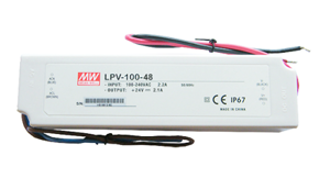
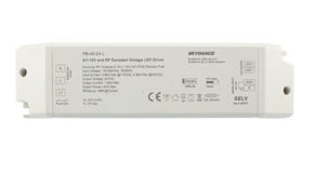
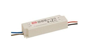
- LED strip power supplies — Complete line 5V, 12V, 24V with CE certification and integrated protections;
- Aluminum profiles — Complete series for recessed, surface, suspension mounting with opal and transparent diffuser covers.
Your most frequent questions about addressable pixel LEDs
How do addressable LEDs work? Addressable LEDs work by integrating an internal control circuit, the driver IC chip, into each individual LED (or pixel). When the controller sends a digital data packet on the line, the first LED in the chain reads its own data bits (24 or 32 bits), updates its brightness and color via internal PWM, and then retransmits the remaining data to the next LED. This process, called "daisy chain", propagates along the entire strip in microseconds, allowing each pixel to be updated individually tens of times per second. The result is the ability to assign each light point one of 16 million possible colors, completely independently from the others. |
What does addressable LED strip mean? An addressable LED strip is an LED strip in which each individual LED (or small group of LEDs called a pixel) can be controlled individually via a digital signal. Unlike standard RGB strips where all LEDs change color in the same way simultaneously, the addressable LED strip allows creating complex dynamic effects, animations, color waves, light scrolling, and any imaginable visual pattern, with each pixel able to have a completely different color and brightness from the others at any time. |
What is WS2812B and how does it differ from SK6812? The WS2812B is the most widespread addressable RGB LED chip in the world, which integrates three LEDs (R, G, B) and a driver IC in a single 5V SMD 5050 package. It uses an 800 Kbps NZR protocol on a single data wire, with 24 bits per pixel in GRB order. The SK6812 is its main competitor and evolution: compatible with the same protocol, but available in RGBW version with a fourth white LED channel for purer whites (CRI>90), higher PWM frequency (1.1 kHz vs 400 Hz of WS2812B, therefore less flickering), and availability in CCT variants. The SK6812 RGBW is the premium choice when white quality is a priority; the WS2812B is the default for purely chromatic projects. |
What is the SPI controller and how is it used? The SPI controller for addressable LEDs is a dedicated hardware device that generates the digital signals necessary to drive pixel LED strips. It receives commands from the user (via app, RF remote, or DMX protocol) and translates them into the specific digital format of the LED chip installed on the strip. To use it: 1) connect the controller's DATA cable to the strip's DIN; 2) connect common GND with the power supply; 3) configure the IC type, color order, and number of pixels via the app or remote; 4) select effects and program scenes. The Skydance WT-SPI controller, available on Ledpoint.it, supports 49 different chip types including WS2812B and SK6812, is controllable via Tuya Smart app, and manages up to 1000 pixels. |
How to make an LED strip work with USB? It is possible to power 5V WS2812B LED strips via USB for light installations (up to 5–10 LEDs at reduced brightness), using a USB cable with bare terminals to connect to the strip's V+ and GND. For control, you can use an Arduino or ESP8266 powered via USB and programmed with FastLED or NeoPixel. However, the maximum current of a standard USB port is 500mA (USB 2.0) or 900mA (USB 3.0), insufficient for strips of significant length at full power. For practical use on longer strips, a dedicated 5V power supply with adequate output current is always preferable. |
What are digital LED strips and how are LEDs activated? Digital LED strips are the alternative name for addressable LED strips; the term "digital" refers to the fact that control occurs via a digital signal (binary data) instead of analog signals (continuous voltages). How are LEDs activated? LEDs in a digital strip activate when the controller sends the data signal containing the color and brightness specification for each pixel. The IC chip in each LED receives its own data packet (24 or 32 bits), interprets it, generates PWM to turn on the RGB LEDs with the required intensity, and maintains the color until the next data update. |
How to calculate the number of pixels for an LED wall? To calculate pixels for an LED wall: 1) Define the physical dimensions of the wall (e.g., 3m × 2m); 2) Choose the strip density (e.g., 60 LED/m); 3) Calculate the number of parallel strips = height / strip pitch (e.g., pitch 10cm = 20 strips for 2m); 4) Calculate total length = number of strips × width (20 × 3m = 60m); 5) Total pixels = total length × density (60m × 60 LED/m = 3600 pixels). A 3600-pixel wall requires controllers capable of managing that number of pixels — for example, 4 WT-SPI controllers of 1000 pixels each, or a more powerful Artnet/sACN controller for professional applications. |
How many colors can an LED pixel have? An RGB LED pixel can theoretically display 16,777,216 colors (256³ = 256 levels for each of the R, G, B channels). With the RGBW variant (SK6812), the white channel is added with an additional 256 levels, extending the color space and improving white rendering. In practice, the difference between adjacent colors in this space is so small as to be invisible to the human eye, making the effective color gamut "infinite" for any application purpose in lighting and design. |
How can I synchronize pixel LEDs with live music? There are several approaches to synchronize addressable pixel LEDs with music: 1) Specialized software like Resolume Avenue, MadMapper, or MilluminOS receives audio in real time, analyzes frequencies via FFT (Fast Fourier Transform), and maps frequency bands to color and intensity effects of the LEDs; 2) Hardware controllers with audio analyzer (like some advanced Skydance models or the Madrix Key for professional events) with line audio input for automatic synchronization; 3) Arduino/ESP32 with MSGEQ7 microphone or audio analyzer modules for DIY installations; 4) MIDI synchronization for precise point-to-point control on groove and beat. For professional events, the most efficient solution is DMX integration between lighting console and Skydance DMX-SPI decoders. |
What are pixel LED spotlights? Pixel LED spotlights are professional stage lighting devices (often used in concerts, theaters, and large-format installations) that internally mount a matrix of addressable LEDs. Each LED in the matrix is an individually controllable pixel, allowing the creation of complex visual effects directly on the light source: graphic patterns, animations, electronically variable zoom and iris effects, all without the use of physical filters or mechanical gobos. Well-known examples are the Robe PixelPati, SGM P-5, and similar. They differ from conventional LED spotlights because the optical head itself is programmable like a mini display. |
What is pixel mapping in an LED installation? Pixel mapping is the process of assigning a virtual X,Y position in space to each physical pixel of an addressable LED installation. Once the installation is mapped, the control software can "project" any graphic or video content onto the physical space: if you correctly map 10 LED strips arranged in parallel on a concert hall wall, you can project a video animation onto that wall as if it were a screen, with the software automatically calculating which pixel must receive which color for each frame. Mapping is typically performed in software like MadMapper, Resolume, xLights, or Madrix. |
Choosing the right addressable LEDs for every project
We have explored the physics of their operation, the architectures of WS2812B and SK6812 chips, SPI communication protocols, programming methodologies both hardware and software, professional applications, and best practices for safe and long-lasting installations. It is now time to put everything together in an operational summary framework that will help you make the right choices for your specific project.
Quick product selection guide
| Project Scenario | Recommended Strip | Recommended Controller | Voltage |
|---|---|---|---|
| Residential staircase lighting (staircase effect) | WS2812B 60 LED/m or SK6812 RGBW 60 LED/m | ES-D(WT) with PIR sensors | 5V |
| Long-run architectural installation (>5m) | WS2812 24V 96 LED/m | WT-SPI Wi-Fi or DS DMX | 24V |
| Premium interior design without visible dots | COB Pixel WS2818 720 LED/m | WT-SPI Wi-Fi | 12V |
| Showroom with CRI>90 white requirement | RGBW WS2814 24V | WT-SPI or DS DMX RGBW | 24V |
| Offices/hospitals circadian lighting | CCT Pixel | CCT pixel-addressable controller | 24V |
| Nightclub/theater/concerts, DMX control | WS2812B 144 LED/m or SK6812 96 LED/m | DS or DS-L DMX-SPI Decoder | 5V/12V |
| High-resolution video effects LED wall | WS2812B 144 LED/m | Artnet/sACN Controller + MadMapper | 5V |
| Prototyping and maker projects | WS2812B 60 LED/m | Arduino/ESP32 + FastLED | 5V |
The five fundamental principles for every successful installation
Before concluding, let's summarize the five principles that, if applied systematically, guarantee the success of any project with addressable pixel LED strips.
- Choose the right chip for the project: there is no universally better chip; the WS2812B is excellent for dynamic RGB effects, the SK6812 RGBW is superior for quality whites, the WS2818 COB is unbeatable for visual continuity. Evaluate specific needs before choosing.
- Correctly size the power supply: an undersized power supply is the number one cause of malfunctions. Calculate the theoretical maximum power and add a 20–50% margin. Provide power injections every 2–5 meters for 5V strips.
- Precisely configure the controller: IC Type, Color Order, and Pixel Length must exactly match the installed strip. Incorrect configuration produces disappointing results even with the best components.
- Protect and dissipate heat: always mount on aluminum profiles to dissipate generated heat, increase component lifespan, and protect the PCB from environmental agents. Do not neglect the IP rating for installations in humid or outdoor environments.
- Choose the controller appropriate to the ecosystem: for home and smart home use, the WT-SPI Wi-Fi is the optimal choice. For professional scenographic installations, the DMX-SPI decoder guarantees integration with professional sector workflows. For stairs and automatic pathways, the ES-D(WT) offers plug-and-play simplicity with PIR sensors.
Addressable LEDs are not simply a technological evolution of lighting: they are a true paradigm shift. Light ceases to be a passive element of space and becomes an active, programmable, interactive medium, capable of telling stories, evoking emotions, guiding behaviors, and radically transforming the experience of any environment. With the right products, a well-configured controller, and the technical knowledge to fully exploit their capabilities, the possibilities are literally infinite.