


LED sensors: how to use them? The definitive guide.
In the landscape of modern lighting, LED sensors represent one of the most significant innovations of recent decades: not mere accessories, but true protagonists of an intelligent ecosystem that connects light, space, and human behavior. Thanks to their ability to detect presence, motion, ambient brightness, or physical contact, these devices enable automatic, efficient lighting that is deeply integrated with the architecture of the spaces we inhabit. The technological evolution of LEDs, combined with the miniaturization of electronic sensors, has opened extraordinary application scenarios: from smart home lighting to industrial security systems, from parking sensors with LED displays to cabinets with automatic light activation—every context can benefit from this synergy. This guide aims to provide a technical and practical response to anyone who wants to understand how LED sensors are used in all their aspects: available types, installation methods, cable management, troubleshooting common issues, and future perspectives. Before delving into technical specifics, it is essential to clarify what LED sensors are and why this technology has become so pervasive in the world of lighting and automation. Strictly speaking, an LED sensor is a device that uses light-emitting diodes—or diodes capable of receiving light radiation—to detect variations in the surrounding environment and translate them into electrical signals usable by a control circuit. LEDs (Light Emitting Diodes) were invented in their modern form in the 1960s, with the first red-light specimens developed by Nick Holonyak Jr. in 1962 at General Electric laboratories. For over two decades, their application remained confined to indicator panels and control lights. It was only with the advent of high-efficiency LEDs in the 1990s, and subsequently with phosphor-based white LEDs in 1996, that interest emerged for more complex applications, including sensor technology. Today, LED sensors integrate analog and digital technologies, wireless communication, artificial intelligence, and advanced microprocessors, constituting an autonomous and rapidly evolving technological sector. From an electronic standpoint, an LED sensor can operate in two main modes: In essence, "LED sensor" refers to all sensors associated with LED lighting systems: PIR motion sensors, radar sensors, touch sensors, twilight sensors, proximity sensors, RGB color sensors, and many others. A generic sensor measures a physical quantity (temperature, pressure, humidity, light) and converts it into an electrical signal. A sensor specifically designed for LED systems must respect additional constraints: compatibility with typical LED supply voltages (12V DC, 24V DC, or 230V AC), absence of electromagnetic interference that could cause flickering, ability to handle low-power loads without minimum current issues, and, in many cases, operation with switching power supplies. Understanding the physical and technological principles underlying LED sensors is essential for choosing the right device, installing it correctly, and optimizing its performance. This chapter explores in depth the mechanisms governing the behavior of these instruments, from semiconductor physics to signal processing chains. The LED is a p-n junction diode. When a forward voltage is applied, electrons cross the junction, recombining with holes and releasing energy in the form of photons—this is the process of electroluminescence. The wavelength of emitted photons depends on the semiconductor material used: GaAs for infrared, GaN for blue and white, AlInGaP for red and orange. Conversely, when the LED junction is reverse-biased (or unbiased), incident photons can generate electron-hole pairs, producing a measurable photocurrent. This property—though less efficient than a dedicated photodiode—is exploited in some innovative applications where the same LED serves as a brightness sensor. Infrared LED sensors exploit invisible IR radiation (typically 850–950 nm) to detect objects or presence. The system consists of: Modulation of the IR signal is fundamental to distinguish the emitted beam from ambient light: without modulation, any infrared source (sun, halogen lamps, warm bodies) could saturate the detector, generating false alarms. PIR sensors (Passive Infrared) are among the most widespread in residential LED lighting. They are called "passive" because they do not emit any radiation but simply detect variations in thermal radiation in the environment. Their operation is based on these key elements: Radar sensors for LEDs typically operate in the ISM bands at 5.8 GHz or 24 GHz, exploiting the Doppler effect. They continuously emit electromagnetic waves and detect the frequency variation of the reflected signal caused by object movement. Compared to PIR sensors, they can penetrate non-metallic materials (glass, wood, drywall), detect even minimal movements, and operate in extreme environmental conditions. Touch sensors for LEDs based on capacitive technology detect the variation in electrostatic capacitance caused by the approach or contact of a finger. An oscillator generates a high-frequency electric field around the sensor electrode: when a conductor (the human body) approaches, capacitance increases, modifying the oscillator frequency. A microcontroller detects this variation and generates the control signal for the LED. These sensors can operate through dielectric materials (glass, wood, plastic) up to thicknesses of 10–15 mm, allowing invisible integration into furniture surfaces. They are available in configurations: The twilight sensor (or twilight switch) contains a photoresistor LDR (Light Dependent Resistor) whose resistance varies inversely with brightness: in full daylight it may have resistances exceeding 1 MΩ, while in darkness it drops to a few hundred Ohms. This element is inserted in a voltage divider connected to a comparator: when the voltage exceeds (or falls below) the set threshold, the comparator switches a relay or triac that controls the LED circuit. More modern models replace the LDR with a silicon photodiode or a digital illuminance sensor (such as TSL2561 or BH1750), ensuring greater linearity, long-term stability, and immunity to temperature changes. Optical sensors in the broad sense use light as a detection medium. Color sensors employ RGB filters with separate photodiodes to measure intensity in the three fundamental color bands. Knowing the contribution of each band makes it possible to calculate the chrominance of the detected color with high precision. These sensors find application in automatic calibration of RGB LED strips, in color temperature control, and in industrial packaging systems for product color verification. The market for LED sensor types is extremely varied and constantly evolving. Each type responds to specific needs and presents distinctive characteristics that make it more or less suitable for certain application contexts. Let's see which ones. In reflective sensors, the LED emitter and detector are positioned on the same side relative to the object to be detected. The emitted radiation is reflected by the object and captured by the detector. This configuration is ideal for applications where it is not possible to position a sensor on both sides (water meters, rotary encoders, label detection on conveyor belts). Detection distance depends on the reflectivity of the target surface and can vary from a few millimeters to several meters. In through-beam sensors (or transmitted-beam sensors), the LED emitter and detector are positioned facing each other. Detection occurs when an object interrupts the light beam between the two elements. They offer the maximum operating distance and highest reliability but require wiring both devices. They are common in industrial counting applications and safety barriers. Slot sensors are a compact version of through-beam sensors, with emitter and detector integrated into a single "U" or "C"-shaped body. The object to be detected passes through the sensor slot. They are very precise and immune to environmental interference. Typical applications: banknote counters, position encoders, gear tooth detection. Proximity sensors detect the presence of objects at short range (typically 2–100 mm) without physical contact. In LED systems for furnishings, they are often integrated into furniture and cabinets to automatically activate internal lighting when doors open. They exist in IR (optical) and capacitive versions, the latter capable of detecting even non-reflective materials such as fabrics and liquids. The best presence sensors for LED lighting are those that combine motion detection with stationary presence detection functions. While a simple PIR turns off if a person stops moving, advanced presence sensors (often based on radar or ultrasonic technology) can keep lights on as long as someone is in the room, even completely still. They are particularly useful in offices, libraries, bathrooms, and meeting rooms. LED motion sensors represent the most widespread and versatile category in the sector. From simple corridor light bulbs to professional installations in industrial environments, these devices have revolutionized the way we manage lighting, combining comfort, safety, and energy efficiency in a single component. Understanding their operation, configuration variables, and selection criteria in detail is essential for optimal installation. The basic principle is simple, but its implementation requires attention to numerous details. When the sensor detects motion within its detection field, it closes the electrical circuit powering the LED luminaire. After a preset time from the last detected motion, the circuit opens and the light turns off. In reality, the process involves several subsystems: Motion-sensor lamps integrate all the components described above into a single luminaire body. In models with E27 or GU10 bases, the sensor is embedded in the reflector or dome; in ceiling spotlights, it is often visible as a small transparent dome on the lower part of the body. The most modern motion-sensor light bulbs also integrate a twilight function that prevents activation when sufficient natural light is still present. LED spotlights with motion sensors for outdoor use are designed for applications requiring high luminous power (500–5000 lm) with coverage of large areas. The integrated PIR sensor typically has a horizontal detection field of 120°–180° and an operating distance of 8–12 meters. Adjustable parameters include: One of the most frequent user questions is: how to keep a motion-sensor light on? Solutions vary: In some situations, it is necessary to know how to disable a motion sensor temporarily or permanently: The most common problems with motion sensors are: Touch sensors for LEDs represent one of the most elegant and innovative solutions for lighting control. Invisible to the eye, integrable into any surface, and virtually free of mechanical parts that could wear out, these devices are becoming a standard in design-oriented residential environments and modern furnishing systems. Understanding their technology and installation methods is essential to fully exploit their potential. The capacitive technology underlying LED touch sensors operates by detecting the variation in electrostatic capacitance caused by the approach of a human finger. The human body, being conductive, acts as a second capacitor plate, modifying the detector circuit's capacitance. A dedicated IC chip (such as the TTP223 or AT42QT1010) continuously measures this variation and generates a digital control signal. Sensitivity can be adjusted by varying the electrode size or through the controller's firmware configuration. Connecting a touch sensor to an LED strip varies depending on the operating voltage and strip type: The applications of touch sensors for LEDs are numerous and constantly expanding: Twilight sensors—also called twilight switches, photocells, or twilight switches—represent the most natural and automatic solution for managing outdoor lighting and some indoor environments. Their operating logic follows the natural rhythm of the day: the light turns on when the sun sets and off when it rises, replicating human behavior without any manual intervention. This simplicity, however, hides fascinating technology and a series of application nuances that are important to understand. The internal circuit of a twilight switch consists of: Lights that automatically turn on at sunset are commonly called "twilight lights", "lamps with photocell", or "spotlights with light sensor". Technically, this is referred to as photoelectric-controlled lighting. The device managing this function can be: Installing an outdoor photocell requires attention to these critical aspects: The LUX adjustment potentiometer allows setting the switching threshold from about 1 lux (near-total darkness) to 100 lux (attenuated daylight). For residential outdoor lighting, the typically used threshold is 10–30 lux, corresponding to astronomical twilight. For illuminated signs that must remain on even during the day in low-light conditions (very overcast sky), higher thresholds are used (50–100 lux). LED sensors for cabinets are one of the most successful examples of integration between LED lighting and proximity sensor technology. The goal is simple, but the result radically transforms the user experience: when the cabinet door opens, the light turns on automatically; when it closes, it turns off. No button to press, no consumption when not needed. Let's see how this technology works and how to choose the best solution for every type of cabinet. For illuminating cabinet interiors, several sensor types are used; let's see which ones. The most economical and reliable solution for hinged-door cabinets. A magnet is applied to the door, a reed switch to the fixed frame: when the door opens, the magnetic field disappears and the reed switch closes the LED circuit. The absence of complex electronic parts makes them virtually indestructible and suitable even in high-humidity environments (bathroom cabinets, wardrobes with damp clothes). For sliding or hinged-door cabinets, where magnetic sensors are not applicable, IR proximity sensors detect the approach of a hand or door. They are discreet, do not require installing a magnet on the door, and work with any material (wood, glass, mirror). Detection distance is typically 5–30 cm. For elegant manual control, touch sensors integrate into the cabinet side panel or shelf. A simple finger touch—even through the wood panel—turns the internal LED strip or step lights on and off. The walk-in closet is a special environment requiring careful lighting design. The main objectives are: uniform visibility of all garments, high color rendering (Ra ≥ 90 to correctly recognize clothing colors), absence of shadows on shelves, and no direct glare. The ideal combination includes: The recommended color temperature for walk-in closets is 4000K (neutral white) to ensure maximum color fidelity of clothing. An LED strip with CRI ≥ 90 is the minimum acceptable for this type of application. The vast majority of LED sensors for furnishings operate at 12V DC, the standard voltage for indoor LED strips. Some models work at 24V DC for high-power strip applications or very long runs. SELV (Safety Extra Low Voltage) power supply is essential for safety in confined environments like cabinets, where the risk of accidental contact with electrical components is higher. Outdoor LED sensors are designed to withstand the environmental stresses typical of open spaces: rain, dust, temperature variations, UV rays, insects, and humidity. Their design must balance mechanical robustness, electrical reliability, and detection precision, under conditions that can vary enormously throughout the seasons. This chapter provides a complete guide to selecting and installing outdoor LED sensors. Optimal positioning of outdoor motion sensors is one of the most critical aspects of installation. Fundamental guidelines are: A common problem in installations with twilight sensors or dimmers is that LED lamps remain on or flicker even with the switch off. Main causes are: Parking LED sensors represent one of the most interesting and rapidly growing application segments in the sector. In multi-story parking lots, shopping centers, airports, and corporate facilities, these systems ensure efficient stall management, reduce time spent searching for available spaces, decrease internal traffic, and improve the overall user experience. Let's examine in detail how they work and what solutions are available. A complete LED car parking sensor system consists of: LED displays for parking lots are designed to ensure maximum readability even in intense light conditions (direct sunlight at entrances) or low light (underground levels). Fundamental technical characteristics are: Retroreflectors for LED sensors are passive devices that reflect the IR beam emitted by the occupancy sensor back to the detector, ensuring stable and precise detection independent of the parked vehicle's reflectivity. They are usually positioned on poles or the front wall of the stall. Their use is preferred in through-beam systems where maximum detection reliability is desired with vehicles of different colors or materials (matte black, chrome, very low cars). According to research conducted by Fraunhofer ISI (Institute for Systems and Innovation) in 2023, implementing intelligent parking management systems based on LED sensors and digital displays leads to: Infrared LED sensors constitute the backbone of countless detection and security systems. Invisible to the human eye, silent, and capable of operating in total darkness, IR LEDs have revolutionized proximity and presence sensor technology. Understanding their operation, applications, and associated retroreflectors is essential for designing LED lighting systems integrated with security functions. IR LEDs for sensor applications typically operate in the following spectral bands: IR barriers (or photoelectric barriers) are widely used security systems in industrial, commercial, and residential settings. An IR LED emits a continuous beam toward a receiver (or a retroreflector). When the beam is interrupted by an object or person, the system generates an alarm or activates a safety device. In retroreflector systems: Retroreflectors for LED sensors used in IR barriers are retroreflective devices that send the light beam back exactly in the direction of origin, regardless of the angle of incidence (within certain limits). This property, called retroreflection, is achieved through prismatic or spherical microstructures on the reflective surface. Selection criteria include: Active infrared LED motion sensors differ from passive PIRs because they actively emit IR radiation and measure its variation over time. They offer: LED strips have become one of the most versatile and widespread lighting elements in residential and professional markets. Their integration with various types of sensors opens practically limitless creative and functional possibilities: from automatic under-stair lighting to kitchen furniture backlighting, from under-cabinet lighting to illuminated bed headboards with touch control. In this chapter, we will deepen every aspect of integration between sensors and LED strips. Not all LED strips are equally compatible with all sensor types. Key factors to consider are supply voltage, power per meter, and driver type: Connecting a motion sensor to a 12V DC LED strip follows this general scheme: For RGB LED strips controlled by motion sensor: LED lamp flickering is one of the most annoying problems and can have several causes when the system includes sensors: Selecting cables for LEDs and sensors is one of the most overlooked aspects of intelligent lighting installations, yet it can make the difference between a reliable, high-performing system and one subject to malfunctions, flickering, and continuous maintenance. Cables of inadequate gauge, unsuitable for environmental conditions, or with insufficient shielding can undermine the best system design. This chapter provides complete guidelines for selecting and installing cables in LED systems with integrated sensors. Cable gauge is chosen based on the maximum current it must carry and the allowable voltage drop along the run. For 12V DC systems, a voltage drop exceeding 3% (0.36V) already causes a visible brightness difference between the beginning and end of the LED strip. Voltage drop formula: ΔV = (2 × L × I × ρ) / S, where L is cable length in meters, I is current in Amperes, ρ is copper resistivity (1.72 × 10⁻⁸ Ω·m), and S is cross-section in mm². In Italy, CEI 64-8 standard (electrical utilization systems) and harmonized CENELEC standards establish minimum requirements for cables used in lighting installations, including LED systems with integrated sensors. Key points to respect: Correct installation of LED sensors is fundamental to ensure expected performance, long-term durability, and system safety. In this chapter, we present detailed operating procedures for the most common sensor types, with particular attention to problems that may arise and the most effective practical solutions. Connecting a 230V AC twilight sensor for controlling outdoor LED lights: Now let's see the steps for installing motion LED sensors: To connect a motion sensor to an existing LED lamp without modifying wall wiring, practical solutions exist: Simplified logical diagram for connecting a 230V AC motion sensor to an LED luminaire: Stair lighting with LED sensors is one of the most appreciated and functional uses of this technology. Not only does it eliminate the risk of tripping in the dark, but it also creates scenographic visual effects of great aesthetic impact, transforming the staircase into a design element. Several technical solutions exist, each with its own characteristics in terms of installation complexity, final effect, and cost. The simplest solution provides an LED strip along the ramp (positioned in the channel under each riser, or laterally in a niche in the wall) controlled by a single PIR sensor at the top or bottom of the stairs. Upon activation, the entire ramp lights up simultaneously for the set time. This system is economical, easy to install, and suitable for small stairs. The most scenographic and appreciated stair lighting system provides a sequential controller that turns on steps one by one, in sequence from top to bottom (or vice versa), simulating progressive activation as one descends or ascends. The system consists of: More advanced controllers allow setting: sequence speed, color (for RGB strips), intensity, on-time duration, and can store different lighting scenes. Aluminum profiles for LED strips are fundamental for an orderly and durable installation on stairs. Models specific for steps include: Each profile includes a diffuser cover (opaque or transparent) that distributes light uniformly, eliminates visible hot spots from individual LEDs, and protects the strip from dust and humidity. The walk-in closet has become a fundamental architectural element in modern homes, and its lighting requires careful design that balances functionality, aesthetics, and energy savings. LED sensors play a crucial role in this context, ensuring automatic light activation upon entry and immediate shutdown upon exit. Before choosing products, it is necessary to answer some fundamental questions: Like any technology, LED sensors present both strengths and limitations. An objective and complete evaluation of these aspects is fundamental for making appropriate choices based on the installation context, available budget, and end-user expectations. LED sensors offer several advantages; let's see which ones. The most immediate and measurable advantage of LED motion sensors is reduced energy consumption. According to data collected by ENEA (Italian National Agency for New Technologies, Energy, and Sustainable Economic Development), installing presence sensors in common work environments (corridors, bathrooms, stairs, meeting rooms) leads to an average reduction in lighting consumption of 40–60% compared to always-on systems. In residential settings, savings range from 20% to 45% depending on occupant habits. Automatic light activation upon entering a dark area eliminates tripping risks, increases perimeter security in case of intrusions, and visually signals the presence of people in industrial corridors where unauthorized entry is dangerous. Lighting automation eliminates the need to search for switches in the dark, always ensures the right amount of light based on actual presence, and can be integrated with home automation systems to create personalized lighting scenes activated automatically based on context. Since LEDs are turned on only when needed, their operational life extends proportionally. If an LED has a nominal life of 25,000 hours with continuous operation, and sensors reduce its on-time to 30% of the total, the effective operational life increases to approximately 83,000 hours, with significant savings on replacement costs. Although they present many strengths, LED sensors show some criticalities that are not always easy to bypass. PIR sensors can be activated by heat sources other than human presence: pets, warm air currents, heaters, sunlight filtered through curtains. Although more advanced models include filters and discrimination logic, the problem is not completely eliminable in all contexts. A standard PIR sensor turns off if a person remains still too long (e.g., while working at a computer or watching television). This behavior is often perceived as annoying and requires the use of presence sensors with radar or ultrasonic technology, which have higher costs. Not all sensors are compatible with all LED drivers and power supplies. Issues of minimum current, leakage current, and electromagnetic compatibility require attention in selection and, sometimes, additional components. The initial investment for quality sensors, dedicated wiring, and possible system programming is higher than a simple traditional switch-based system. Return on investment is typically realized in 1–3 years thanks to energy savings. Integrating LED sensors into more complex electronic systems requires understanding various electronic components that work in synergy. This chapter is dedicated to designers, specialized installers, and all those who want to go beyond simple plug-and-play installation, understanding the deep mechanisms governing the behavior of these systems. Modern LED sensors integrate 8- or 32-bit microcontrollers (such as STM32, PIC, AVR, or ESP32 series) that perform fundamental functions: The LED driver (constant current or constant voltage power supply) is the component that actually powers the LED diodes. Its compatibility with the control sensor is fundamental to avoid problems. Critical points are: LED dimming can occur in two modes: Advanced touch dimmer sensors combine both technologies to ensure smooth and stable dimming across the entire 1% to 100% range without flickering and without color shift. RGB sensors and color sensors for LEDs represent the most advanced level of optical sensor technology applied to lighting. Their ability to precisely measure the chromatic composition of ambient light or illuminated objects opens sophisticated application scenarios ranging from photography to industrial quality control, from adaptive home automation to professional visualization systems. An RGB sensor is an optoelectronic device that separately measures light intensity in the three components of the RGB color model: red (Red, ~620–750 nm), green (Green, ~500–565 nm), and blue (Blue, ~450–490 nm). Internally, it uses three separate photodiodes, each with an optical bandpass filter that passes only the color band of interest, and a current-to-voltage conversion circuit to generate three analog or digital signals proportional to intensity in each band. The most common color sensor for LED applications is the 4-photodiode type: three with RGB filters and one without filter (broadband) for total brightness measurement. Combining these four values, the integrated microcontroller calculates: In colored LED systems, the application of LED sensors requires the sensors to perform additional operations, namely: LED dimming combined with intelligent sensors represents the highest level of lighting control, allowing real-time adaptation of light levels to environmental conditions and user preferences. This technology, once the exclusive domain of large commercial buildings, is now accessible even in the residential segment thanks to cost reductions and greater availability of consumer products. As explained in the components chapter, LED dimming occurs primarily via PWM method. PWM frequency is fundamental: frequencies below 100 Hz produce visible flickering; frequencies above 1 kHz eliminate any perception of flicker. Quality dimmers operate at 8–24 kHz to ensure maximum visual comfort even in peripheral vision conditions or in the presence of movement. The most sophisticated systems integrate an ambient brightness sensor (e.g., DALI-2 with standard sensor interface) that continuously measures the natural light level in the environment and automatically adjusts LED power to maintain constant illuminance on the work plane (e.g., 500 lux for offices, 300 lux for corridors). This system, called daylight harvesting, maximizes energy savings by making the most of available natural light. Even with careful installation, LED sensors can exhibit unexpected behavior. Let's review the most frequent problems reported by users and practical solutions to overcome them. The problem of LEDs not turning off completely (remaining slightly illuminated even with switch open or sensor in "off") has three main causes: LED flickering can have several causes: If sensor lights remain always on, possible causes are: For window opening sensors (magnetic reed), correct positioning is: The LED sensor sector is in technological ferment. Ongoing innovations are redefining the boundaries of application possibilities, leading toward increasingly intelligent, miniaturized, efficient, and digitally integrated systems. This chapter explores the most significant trends and technologies that will shape the future of sensorized lighting. LiDAR (Light Detection And Ranging) technology, made famous by its use in self-driving cars, is finding applications in the field of lighting sensors. An emitter laser or IR LED measures the time-of-flight (ToF) of the reflected beam to construct a three-dimensional map of the environment in real time. Advantages include: precise detection of the position and number of people in the environment, 3D space mapping, immunity to thermal interference, and adaptive optimization of lighting based on the actual distribution of people in the environment. New LED sensors integrate microprocessors capable of executing machine learning algorithms directly in the device (edge AI), without the need for cloud connectivity. These systems can: Li-Fi (Light Fidelity) is an emerging technology that uses very rapid variations in LED light intensity (invisible to the human eye) to transmit digital data, analogously to Wi-Fi but via light. A photodiode sensor integrated in the environment (or in the user's device) receives these light signals, converting them into data. Theoretical speeds reach 224 Gbit/s in the laboratory; today's commercial applications are around 100 Mbit/s. Li-Fi is particularly interesting in environments where radio waves are undesirable (hospitals, airplanes, RF-sensitive industrial environments). One of the historical challenges in sensor installation is the need for electrical power and wiring. New sensors with energy harvesting collect energy from the environment (ambient light via small photovoltaic panels, vibrations, temperature differences) to power themselves autonomously, eliminating the need for batteries or cables. Paired with low-power wireless protocols (Zigbee, EnOcean, BLE), they allow installation of sensors virtually anywhere without electrical system intervention. Human-Centric Lighting is an approach to lighting that takes into account the effects of light on people's physiological and psychological well-being. HCL systems use brightness and color temperature sensors to automatically adjust LED lighting throughout the day, mimicking the natural cycle of sunlight: cool white, intense light in the morning (to stimulate attention), neutral white light during working hours, warm and soft light in the evening (to promote relaxation and sleep). Research conducted by WELL Building Standard and Illuminating Engineering Society demonstrates that well-designed HCL systems can increase productivity by 10–15% and improve occupants' sleep quality. The global LED sensor market is experiencing sustained and structural growth. The transition toward energy efficiency, the spread of home automation, and the increasingly deep integration between lighting and IoT are driving growing demand across all segments: residential, commercial, industrial, and infrastructural. Sources: Allied Market Research, Grand View Research, MarketsandMarkets — editorial elaboration LEDpoint.it The consumption of a PIR sensor is extremely low: The cost of a light/motion sensor varies significantly depending on quality and features: In this chapter, we collect answers to the most frequent questions that users, installers, and designers ask about LED sensors, with clear, precise, and immediately usable answers for daily practice. The function of a sensor is to detect a physical or chemical quantity (brightness, temperature, motion, pressure, color, humidity) and convert it into an electrical signal processable by a control circuit. In LED lighting systems, the sensor converts the detected environmental variation into a signal that activates, deactivates, or adjusts the light level of the LEDs. Types of sensors are numerous. According to the detected quantity, they are classified as: physical sensors (temperature, pressure, force, acceleration, position, motion, light, sound), chemical sensors (gas, pH, humidity, molecule concentration), biological sensors (biosensors, DNA/protein detection). In the field of optical sensor technology applied to LEDs alone, dozens of different types are counted. Technological sensors in the field of LED lighting detect: presence and motion of people, ambient brightness level, color temperature of natural light, capacitive touch, object proximity, door and window opening, color of illuminated objects, sound level (some home automation applications), temperature and humidity (to correct LED performance). The best motion detector depends strongly on the application: The best presence sensors for indoor LED lighting are those based on 24 GHz radar technology, as they detect even minimal movements (breathing, slight shifts), keeping lights on even with completely stationary people. Reference brands in the professional segment include Osram/Siteco, Schneider Electric, Hager, Gewiss, and Legrand. Light sensors for LEDs work by measuring the intensity of incident light radiation using photodiodes, phototransistors, or photoresistors. The variation in electrical resistance (LDR) or generated current (photodiode) is processed by a comparator circuit that compares the value with the set threshold and switches the LED circuit accordingly. The light sensor (twilight) is connected to the LED strip via the power supply: the sensor is inserted in series with the 230V AC phase conductor that powers the LED strip 12V or 24V driver/power supply. Alternatively, for already-installed low-voltage systems, a specific 12V DC or 24V DC sensor is used that is inserted directly into the DC power line. To mount an outdoor photocell: choose a point sheltered from direct sun (north or east-facing wall), drill the wall or ceiling to pass cables, connect Phase (L), Neutral (N), and Load (OUT) according to the manufacturer's diagram, secure the body to the wall with screws, set the LUX threshold, and test. Positioning away from controlled lamps is fundamental to avoid feedback. Color sensors contain separate photodiodes equipped with optical filters for the red, green, and blue bands of the visible spectrum. By measuring the relative intensity in the three bands, the microcontroller calculates the chromatic coordinates of the illuminated object or analyzed light source. The output can be in CIE XYZ, sRGB format, color temperature (K), or directly as a correction signal for the LED system. From semiconductor physics to wireless communication protocols, from simple magnetic cabinet sensors to sophisticated LiDAR systems with artificial intelligence, the landscape of LED sensors is rich, varied, and full of opportunities for anyone who wants to improve their quality of life, reduce energy consumption, and enhance the spaces they inhabit or design. It is right to choose them while remaining aware that: Once this awareness is integrated, it is possible to choose with complete peace of mind and realize a lighting project that will provide great satisfaction in the long term.What are LED sensors?
Origin of LEDs and LED sensors
How does an LED sensor work?
Difference between LED sensors and detectors
Sensor type Detected quantity Technology Typical LED application PIR (Passive Infrared) Body heat/motion Pyroelectric Stair lights, exteriors, garages Microwave/Radar RF field variation Doppler 5.8–24 GHz Corridors, warehouses, bathrooms Ultrasonic Ultrasound reflection Piezoelectric 40 kHz Parking lots, dark rooms Capacitive Touch Electrostatic capacitance variation Capacitive LED strips, table lamps Twilight (LDR) Ambient brightness Photoresistor Nighttime exterior lighting Active Infrared IR beam interruption IR LED + photodiode Intrusion systems, barriers Proximity Short-range presence Reflected IR / capacitive Cabinets, drawers, furniture Color/RGB Light wavelength Multiband photodiodes Display calibration, packaging
Operating principles of LED sensors
The LED diode as emitter and detector
Physics of infrared detection
How PIR sensors work
Operating principle of radar/microwave sensors
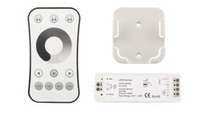
Capacitive sensors: touch technology
How twilight sensors work
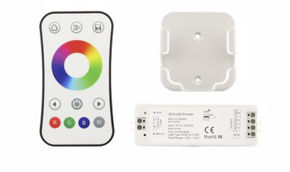
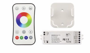
How optical and color sensors work
Parameter PIR Sensor Radar Sensor Touch Sensor Twilight Sensor Supply Voltage 3–15V / 230V AC 3.3–12V DC 3.3–24V DC Typically 230V AC Power Consumption 0.5–1 mA 30–60 mA 1–5 mA 1–3 mA Detection Distance 3–12 m 3–20 m 1–15 mm N/A (ambient brightness) Detection Angle 90°–120° 360° or directional Point-based Open field Response Time 50–500 ms <100 ms <50 ms 2–60 s Susceptibility to False Alarms Medium Low Very low Low Indicative Cost €5–35 €10–60 €8–30 €5–20
Types of LED sensors
Reflective sensors
Through-beam sensors
Slot sensors (Interruption Sensors)
LED proximity sensors
Presence sensors
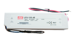
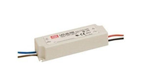
Classification by supply voltage
Category Voltage Typical application Safety SELV (Safety Extra Low Voltage) 12V DC or 24V DC Indoor LED strips, cabinets, stairs Maximum – no electrician required Low Voltage 48–120V DC Industrial systems, automotive High – qualified intervention required Mains Voltage 230V AC (50 Hz) Spotlights, outdoor sensors, parking lots Standard – requires electrician
LED motion sensors: complete guide
How motion-sensor LED lights work
How motion-sensor lamps work
How LED spotlights with motion sensors work
How to install two motion sensors on the same circuit
Installing two motion sensors in series or parallel on the same LED circuit is a common solution to cover large areas or ensure control from multiple points. Possible configurations are:How to keep motion-sensor lights on
How to disable a motion sensor
Why the motion sensor doesn't work or turns on by itself
Problem Probable cause Solution Sensor does not activate Sensitivity at minimum, object out of range, LUX too high Increase sensitivity, reorient sensor, reduce LUX threshold Sensor turns on by itself Pets, heaters, sunlight, warm air currents Reduce sensitivity, shield from heat sources, use radar sensor Light turns off too soon Timer at minimum, person out of range Increase TIME, reposition sensor Light stays on continuously Override active, relay fault, continuous signal Sensor reset, wiring check, replacement Flickering at startup Incompatibility with LED switching power supply Use LED-compatible sensor or add dummy load resistor
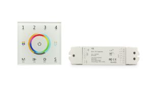
Touch sensors for LEDs
How touch sensors for LEDs work
Types of touch sensors for LEDs
How to connect a touch sensor to an LED strip
Practical applications of LED touch sensors
Twilight sensors for LEDs
How a twilight switch works
Lights that turn on when it gets dark
How to install a twilight photocell
Adjustment and calibration of the twilight sensor
LED sensors for cabinets
Available technologies for automatic cabinet lighting
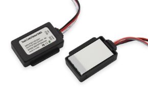
Magnetic reed sensors
IR proximity sensors
Touch sensors for furniture
How to light a walk-in closet
How many volts are needed for cabinet LED sensors
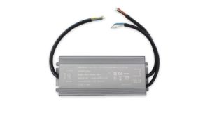
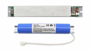
Outdoor LED sensors
IP protection ratings for outdoor LED sensors
IP rating Solid protection Liquid protection Typical application IP44 Objects > 1mm Water splashes Covered porch, protected entrance IP54 Limited dust Splashes from any direction Sheltered exterior wall IP65 Total dust protection Water jets Standard outdoor, exposed wall IP66 Total dust protection Powerful water jets Industrial environments, marine IP67 Total dust protection Immersion 1m/30min Buried sensors, pools IP68 Total dust protection Prolonged immersion Underwater applications
Where to position outdoor motion sensors
Why LED lamps stay on with the switch off
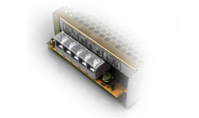
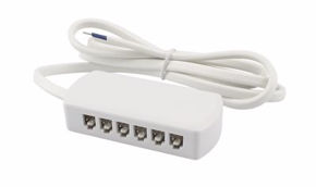
Parking LED sensors
LED car parking sensor systems
Parking LED display sensors
Characteristic Typical value Notes Brightness 5000–10000 cd/m² Automatically adjustable Pixel pitch 10–20 mm Smaller = higher resolution Protection rating IP54 minimum IP65 for exposed areas Operating temperature -20°C / +60°C Heated versions for cold climates Communication protocol RS485, Modbus, TCP/IP TCP/IP for advanced systems Viewing angle 120°–140° Lateral visibility in corridors
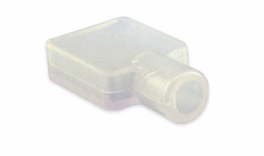
Retroreflectors for LED sensors in parking lots
Economic and environmental advantages of LED parking systems
Infrared LED sensors and retroreflectors
Technical characteristics of infrared LEDs
Band Wavelength Semiconductor material Main application NIR (Near Infrared) 780–1000 nm GaAs, AlGaAs Remote controls, proximity sensors, biometrics SWIR (Short-Wave IR) 1000–2500 nm InGaAs Industrial quality control, security Specific 850 nm 850 nm GaAlAs Night-vision surveillance cameras Specific 940 nm 940 nm GaAlAs Remote controls, PIR sensors, barriers
How infrared beam barriers work
Retroreflectors for LED sensors: selection and installation
Infrared LED motion sensors: differences from classic PIRs
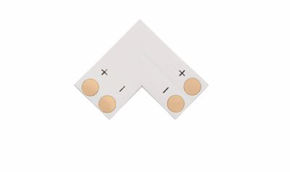
Sensors for LED strips: complete integration guide
Types of LED strips compatible with sensors
LED strip type Voltage Motion sensor Touch sensor Twilight sensor Monochrome LED 12V 12V DC Yes (12V sensor) Yes Yes (with power supply) Monochrome LED 24V 24V DC Yes (24V sensor) Yes (24V compat.) Yes (with power supply) RGB LED 12V 12V DC Yes (activates white) Yes (RGB touch) Fixed color only RGBW LED 12V 12V DC Yes (activates white) Yes (RGBW touch) Fixed color only COB LED 12V 12V DC Yes Yes Yes 230V AC Strip 230V AC Yes (230V PIR) Limited compatibility Yes (standard photocell)
How to connect a motion sensor to an LED strip
How to avoid LED strip flickering with sensors
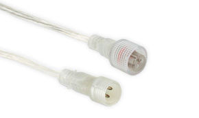
Cables for LEDs and sensors: selection and installation guide
LED strip cable gauge: practical calculation
LED Strip Power Current (12V) Length <5m Length 5–10m Length >10m Up to 30W 2.5A 0.75 mm² 1.5 mm² 2.5 mm² 30–60W 5A 1.5 mm² 2.5 mm² 4 mm² 60–120W 10A 2.5 mm² 4 mm² 6 mm² 120–240W 20A 4 mm² 6 mm² 10 mm²
Cable types for LED systems with sensors
Regulations
How to install and connect LED sensors: practical step-by-step guide
How to connect a twilight light sensor
How to mount a wall motion sensor
How to connect a motion sensor to a lamp
How to connect a motion sensor for lights: block diagram
How to light stair steps with LED sensors
Systems with LED strip and single motion sensor
Sequential step systems with dedicated controller
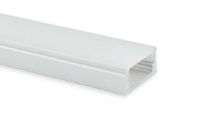
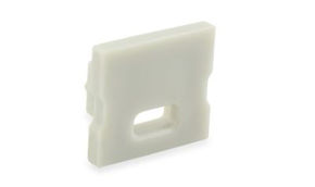
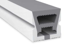
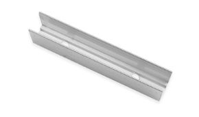
How to light interior stairs with aluminum profiles
How to light a walk-in closet
Walk-in closet lighting planning
Complete lighting solution with LED sensors
Zone Lighting type Sensor Color temperature CRI General ceiling LED ceiling light or downlight Ceiling PIR sensor 4000K ≥80 Clothing rails LED strip under rail Magnetic door sensor 4000K ≥90 Shelves Front LED strip Touch or magnetic sensor 4000K ≥90 Drawers Micro LED strip Magnetic drawer sensor 3000K ≥80 Makeup mirror Perimeter mirror LED Touch sensor 3000–4000K ≥95
Advantages and disadvantages of LED sensors
Main advantages of LED sensors
Documented energy savings
Greater safety
Comfort and practicality
Increased LED lifespan
Limitations and disadvantages of LED sensors
False alarms from PIR sensors
Inability to detect stationary presence (standard PIR)
Compatibility with existing LED systems
Initial cost
Sensor type Main advantages Main disadvantages Indicative cost PIR Low cost, reliable, widespread False alarms, no stationary presence detection €5–35 Radar High precision, stationary presence detection, penetrates walls Higher cost, possible interference €15–80 Capacitive Touch Aesthetics, no moving parts, silent Requires calibration, sensitive to water €8–35 Twilight Natural automation, very simple Critical positioning, drift over time €5–20 Ultrasonic Detects small movements, works in darkness Ultrasonic noises annoying to pets €10–40
Components and integration of LED sensors in complex circuits
The microcontroller at the heart of the LED sensor
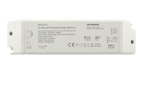
LED drivers and compatibility with sensors
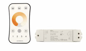
How LED dimming works
Communication protocols for intelligent LED sensors
Protocol Type Distance Number of nodes Typical application DALI (IEC 62386) Wired 300m 64 per segment Commercial buildings, offices DMX512 Wired 300m 512 channels Stage lighting, architectural KNX Wired/RF 1000m 57,375 Advanced residential home automation Zigbee Wireless 100m (mesh) 65,000 Smart home, IoT Z-Wave Wireless 100m (mesh) 232 Premium smart home Bluetooth LE Wireless 50m Variable Smartphone apps, retrofit Wi-Fi 802.11 Wireless 50m (indoor) Variable Cloud IoT, Alexa/Google integration 1-10V Analog wired 50m 1 per circuit Simple industrial dimming
RGB sensors and color sensors: advanced applications
What is an RGB sensor
How color sensors work
Applications of color sensors in LED systems
Dimming and LED sensors: a brief overview
How LED dimming works
Dimmers with ambient brightness sensor
Common problems with LED sensors and related solutions
Why LEDs don't turn off completely
Why the LED flickers
Why sensor lights stay on continuously
Where to position window sensors
Emerging technologies and innovations in LED sensors
LiDAR applied to LED sensors
LED sensors with edge artificial intelligence
Li-Fi: data communication via LED
Wireless LED sensors with energy harvesting
Human-Centric Lighting (HCL) and circadian sensors
Market data, statistics, and surveys on the LED sensor sector
Global market size
Year Market value (Billion USD) Annual growth rate Main driver 2020 2.1 — Residential LED retrofit 2021 2.4 +14% Post-pandemic smart home 2022 2.8 +17% EU energy efficiency directive 2023 3.2 +14% IoT and connected lighting 2024 3.7 +16% Edge AI, HCL, parking sensors 2025 (estimate) 4.3 +16% Li-Fi, energy harvesting, edge AI 2028 (forecast) 6.8 +12% CAGR Smart cities, Industry 4.0
Distribution by sensor type (market share 2024)
Type Global market share Trend PIR Sensors 42% Stable (mature market) Radar/Microwave Sensors 23% Strong growth (+25% annually) Capacitive Touch Sensors 15% Growth (+18% annually) Twilight Sensors 10% Stable IR Proximity Sensors 6% Moderate growth Others (color, LiDAR, ToF) 4% Strong potential growth
Documented energy savings in main application contexts
Application context Average energy savings Source Offices (corridors, bathrooms) 40–60% ENEA, 2023 Multi-story parking lots 35–50% IEA, 2022 Warehouses and industry 45–65% DOE US, 2022 Residential outdoor lighting 25–40% ANIE Federation, 2023 Condominium stairs and corridors 50–70% ENEA, 2022 Homes (presence sensors) 20–35% Fraunhofer ISE, 2023
How much does a PIR sensor consume and how much does it cost
FAQ: frequently asked questions about LED sensors
What is the function of a sensor?
What are the types of sensors and how many exist?
What do technological sensors detect?
What is the best motion detector?
What are the best presence sensors?
How do light sensors work?
How do you connect a light sensor to an LED strip?
How do you mount a photocell?
How do color sensors work?
LED sensors: choosing with awareness