


Luminous flux and degradation: causes and prevention
Luminous flux represents the total quantity of light emitted by a light source in all directions, measured in lumens. In professional LED installations, a thorough understanding of this parameter and the degradation phenomena that affect it over time is fundamental to ensuring optimal performance, energy efficiency, and return on investment. This article provides a comprehensive, technical, and practical treatment of luminous flux, its related parameters, and strategies to prevent and mitigate degradation in professional lighting systems. Through detailed analysis, statistical data, case studies, and technical tables, we will explore the mechanisms, causes of performance decay, and best practices for maintaining high light intensity levels over the long term, with particular attention to commercial, industrial, and infrastructure applications. Before addressing degradation, it is essential to establish fundamental photometric concepts. We will therefore review all relevant quantities, their mathematical relationships, and their practical significance in the design and evaluation of LED systems. Luminous flux (Φ) is a photometric quantity that quantifies the luminous power perceived by the human eye, emitted by a source in all spatial directions. It does not measure total radiant energy, but only the visible component, weighted according to the spectral sensitivity curve of the average human eye (photopic V(λ) curve). While radiant power (watts) measures all emitted electromagnetic energy, luminous flux (lumens) measures only the portion visible to our eyes, applying a spectral weighting factor. This is fundamental for comparing sources with different spectral distributions. The mathematical definition of luminous flux begins with its relationship to luminous intensity. For a non-isotropic source, the total flux is obtained by integrating the luminous intensity I(θ,φ) over the entire solid angle (Ω): Φ = ∫ I(θ,φ) dΩ (integral extended over 4π steradians) Where: For sources with approximately symmetric distribution, the formula can be simplified. For example, for uniform emission within a solid angle cone Ω, the formula becomes: Φ = I * Ω. Luminous flux does not exist in isolation. For a complete evaluation of a lighting system, it must be considered together with three other fundamental quantities: luminous intensity, illuminance, and luminous efficacy. Luminous intensity (I) is the photometric quantity that describes the luminous power emitted by a source in a particular direction. Its unit of measurement is the candela (cd). Unlike flux (total), intensity is directional. Purpose of luminous intensity: Luminous intensity serves to: What does luminous flux express in relation to intensity? It expresses the "sum" of all luminous intensities emitted in every direction. If intensity is the "directional detail", flux is the "global total". Illuminance (E) measures the incident luminous flux per unit area. Its unit is the lux (lx), equivalent to one lumen per square meter (lm/m²). Fundamental difference between lumens and lux: Lumens (flux) describe the source's output. Lux (illuminance) describe how much of that light actually reaches a specific plane (a desk, a road, a workbench). 10,000 lumens emitted toward the sky will produce no useful lux on the ground. The relationship is given by: E = Φ / A (for uniform incident flux over area A), but generally depends on distance and angle of incidence (Lambert's cosine law). Luminous efficacy (η) is the ratio between the total emitted luminous flux (Φ in lm) and the absorbed electrical power (P in W). It is measured in lumens per watt (lm/W). This parameter is crucial for evaluating the operating economy of an installation. Modern LEDs for professional applications regularly exceed 150 lm/W, with the most advanced models approaching 200 lm/W in laboratory conditions. Luminous flux degradation, known as Lumen Depreciation (L), is the irreversible process of reduction in a LED's light output over time. Understanding its physico-chemical causes is the first step toward developing effective mitigation strategies. This phenomenon is not a simple "failure" but a progressive degradation influenced by multiple factors. Within the semiconductor, several microscopic mechanisms lead to reduced efficiency of radiative recombination (which produces photons). High current densities and elevated junction temperatures accelerate the diffusion of impurity atoms and the migration of lattice defects (such as vacancies and dislocations) into the LED's active regions. These defects act as non-radiative recombination centers, where electron energy is dissipated as heat instead of being converted into light. Studies on InGaN LEDs show that increasing junction temperature from 85°C to 135°C can accelerate the flux degradation rate by up to 5 times. White light LEDs typically use a blue-emitting chip (InGaN) coated with a phosphor converter (e.g., YAG:Ce). This phosphor layer is subject to: Phosphor degradation leads not only to flux reduction but often also to a shift in correlated color temperature (CCT) toward cooler (or warmer, depending on phosphor chemistry) tones. Often, the rate of luminous flux degradation is determined more by operating conditions and overall system quality than by the LED chip itself. Junction temperature (Tj) is the single most influential parameter on LED lifetime. The relationship is exponential. Arrhenius' empirical rule, often applied, suggests that for every 10°C reduction in Tj, LED useful life approximately doubles. Statistical data A study by the U.S. Department of Energy (DOE) on LED modules for general lighting showed that maintaining Tj at 105°C instead of 135°C reduces lumen loss after 36,000 hours from 30% to less than 15% for medium-quality products. *Average indicative values for commercial/professional quality LEDs. **L70 = Hours to 30% reduction of initial flux. LEDs are driven by constant current. Operating above the nominal current (overdriving) drastically increases thermal and electrical stress, accelerating all degradation mechanisms. A 10% current increase can lead to a 40% increase in power dissipation and a 15-20°C rise in Tj in a system with non-optimal thermal management. Current quality is also crucial. High current ripple (e.g., > 30% of DC current) causes thermomechanical fluctuations in the chip and interface materials, leading to microcracks and delamination. High-quality drivers for professional installations typically maintain ripple below 10%. In industrial or outdoor environments, LEDs may be exposed to: Accurately predicting long-term LED behavior is essential for evaluating lifecycle costs and planning maintenance. This chapter explores international standards and mathematical models that enable estimation of luminous flux degradation, transforming laboratory data into reliable real-world projections. The LED lighting industry relies on two complementary standards developed by the Illuminating Engineering Society of North America (IESNA), which have become the global reference for characterizing lumen maintenance. The IES LM-80-20 standard ("Approved Method: Measuring Luminous Flux and Color Maintenance of LED Packages, Arrays and Modules") defines uniform procedures for measuring variations in luminous flux and chromaticity of LED sources (packages, arrays, modules) over time under controlled environmental conditions. Critical aspects of LM-80 The LM-80 report provides raw measurement data, typically in the form of a graph or table showing lumen maintenance (expressed as a percentage of initial value) versus time for each test temperature. The IES TM-21-11 (and subsequent revisions) standard ("Projecting Long Term Lumen Maintenance of LED Light Sources") provides the method for extrapolating LM-80 data (typically 6,000–10,000 hours) to project LED behavior up to 36,000 hours (approximately 10 years at 10 hours/day) or, in some cases, beyond. The core of TM-21: exponential degradation equation TM-21 assumes that luminous flux degradation follows an exponential trend after an initial stabilization period. The mathematical model used is: Φ(t) = B * e^(-αt) Where: TM-21 rigorously defines how to calculate parameter α from the latter portion of LM-80 data (typically from 5,000 hours onward) using a least-squares method. Fundamental limitation: The standard prohibits projecting beyond 6 times the duration of collected data. Therefore, from 10,000-hour LM-80 data, the maximum allowed projection is to 60,000 hours. LED useful life is not defined by "failure" but by reaching a certain percentage reduction of initial luminous flux. Lxx represents the time (in hours) after which luminous flux has reduced to xx% of its initial value. Examples: Industry statistical data: An aggregated analysis of 200 LM-80/TM-21 reports from global manufacturers (2020–2023) shows that for professional-quality LEDs operated at Ts=85°C, the average projected L90 value at 60,000 hours is approximately 45,000 hours, with a range from 30,000 hours (entry-level products) to over 70,000 hours (high-end products). In professional lighting design according to standards such as EN 12464 series, the LLMF (Lamp Lumen Maintenance Factor) is a multiplier ≤1 applied to initial flux to account for expected degradation at the end of the planned maintenance period. A designer specifying a product with L90=50,000 hours for an installation with a 5-year maintenance cycle (approximately 22,000 hours at 12h/day) can use an LLMF of 0.92–0.95, reducing initial oversizing and saving energy. Ignoring LLMF leads to oversized installations at commissioning that degrade toward acceptable levels but waste energy for years. Understanding degradation causes and models enables implementation of proactive strategies to control them. This chapter provides a detailed framework of concrete actions, from design phase to operational management, to maximize luminous flux stability over time. The primary objective is to minimize junction temperature (Tj). This is achieved by managing the entire thermal chain from chip to environment. Materials: extruded aluminum (with thermal conductivity ~200 W/mK) is the standard. For very high thermal loads or limited spaces, copper alloys (~400 W/mK) or, in cutting-edge applications, carbon-matrix composites (diamond composites, up to 1500 W/mK) are used. Geometry (fins): efficiency depends on exchange surface area. The relationship is not linear: doubling fin height does not double heat exchange due to decreasing thermal gradient along the fin. CFD (Computational Fluid Dynamics) simulation software is essential for optimizing fin thickness, spacing, and profile based on natural or forced airflow. Surface finish: a black paint with high thermal emissivity (ε > 0.9) can increase radiative exchange by 20–30% compared to natural anodized aluminum (ε ~ 0.7–0.8), especially without forced ventilation. The layer between the LED module and heat sink is a critical point of thermal resistance. Silicone-based thermal greases (Rth ~ 0.2–0.5 K/W for a typical area) are common. For superior performance: Correct TIM application is fundamental: excessive thickness or air bubbles dramatically increase resistance. A University of Padua study showed that non-uniform thermal grease application can cause Tj differences of up to 15°C between identical LEDs on the same heat sink, leading to differential degradation and visually non-uniform aging of the luminaire. A quality driver must guarantee: Lenses and reflectors must maintain their optical properties. PMMA (Acrylic) is economical but yellows under UV and high temperatures (above 80°C). PC (Polycarbonate) is more heat-resistant but can yellow. For professional applications, high-transmittance optical silicone and borosilicate glass are superior choices, with operating temperatures up to 150°C and excellent UV stability. Optics degradation can absorb or scatter 10–30% of light, mimicking LED degradation itself. Operating LEDs below nominal power is one of the most effective strategies for dramatically extending their life. Derating: design the installation to use LEDs at 70–80% of their maximum nominal current. For example, use a 100W module in a thermally limited luminaire rated for 75W. This immediately lowers Tj by 10–20°C, exponentially increasing L70/L80 life. Dimming: operation at reduced levels (e.g., 70% in offices at night) not only saves energy but proportionally reduces generated heat. The relationship between current and flux is nearly linear, while the relationship between current and heat (dissipated power) is super-linear due to increased series resistance with temperature. Dimming to 50% can increase L70 life by 3–4 times. Advanced systems for outdoor or hot environments integrate a temperature sensor on the heat sink. When a critical threshold is exceeded (e.g., 80°C on the body), the driver progressively reduces current (and therefore flux) to keep Tj within safe limits, preventing accelerated degradation. This is an intelligent compromise between immediate performance and long-term durability. Theory meets practice. This chapter analyzes real degradation scenarios, their root causes, and implemented solutions, providing a repertoire of immediately applicable knowledge. Scenario In a 1,000 m² open-plan office with linear suspended LED luminaires (3000K, 4000 lm each), after 3 years (approximately 8,000 hours) visible non-uniformity in illuminance is observed. Some rows appear "cooler" and less bright. Investigation and causes Solutions implemented Result After intervention, non-uniformity was corrected. Projections based on the new thermal profile indicate L80 life exceeding 60,000 hours for all luminaires. Scenario On a seaside promenade, after 4 years, 30% of architectural LED floodlights on poles show drastic flux reduction (>40%) and visible corrosion. Investigation and causes Solutions implemented Transitioning from corrective or time-based scheduled maintenance to condition-based predictive maintenance is the evolutionary step to maximize operational efficiency and prevent costly plant shutdowns. This chapter describes technologies and methodologies for real-time monitoring of luminous flux health status. Controlled lighting networks (DALI-2, Zigbee, Bluetooth Mesh, LoRaWAN) serve not only for on/off control but can become distributed sensor networks. Raw data must be transformed into actionable information. Software platforms aggregate data from thousands of light points, presenting: Alerts automatically generate work orders in the CMMS (Computerized Maintenance Management System), directing technicians to the correct luminaire with the right spare part and preliminary diagnosis, reducing intervention times by 60–70%. Benefit statistics: a study conducted on a portfolio of 50,000 light points managed with predictive maintenance showed a 40% reduction in total maintenance costs compared to scheduled maintenance, a 15% increase in average system efficiency (because degraded luminaires are repaired before consuming excess energy), and zero catastrophic failures causing dark zones. We summarize in an operational decalogue the most critical actions for preserving luminous flux in professional installations, integrating concepts discussed in previous chapters. Research aims to mitigate degradation causes at their root: LEDs on gallium nitride (GaN) substrates on silicon or larger-diameter sapphire reduce crystal defects; quantum dot (QD) phosphors offer greater thermal and spectral stability; COB (Chip on Board) with ceramic substrates dramatically improve heat extraction. The synergy between advanced materials, intelligent control electronics, and data management promises to bring future LED installations toward L90 useful lives exceeding 100,000 hours, making luminous flux degradation an increasingly marginal phenomenon—though its understanding will remain fundamental for anyone designing, installing, or managing quality lighting. Understanding luminous flux and the complex degradation phenomena affecting it is a non-negotiable requirement for designing and managing efficient, durable, and economically advantageous professional LED installations. The key lies in rigorous junction temperature control, selection of high-quality components with reliable data, design of an effective thermal system, and adoption of a data-driven maintenance approach. By implementing the strategies illustrated in this guide, designers, installers, and facility managers can ensure that LED installations deliver optimal and consistent luminous performance, maintaining high luminous flux for tens of thousands of hours, thereby maximizing return on investment and sustainability of lighting interventions.Luminous flux: what is it?
What is luminous flux? Fundamental definition
Symbol and unit of measurement of luminous flux
Luminous flux is conventionally denoted by the Greek letter Phi (Φ) or, less frequently, by the letter F. Its unit of measurement in the International System is the lumen (lm). One lumen is defined as the luminous flux emitted into one steradian (unit of solid angle) by an isotropic point source with a luminous intensity of 1 candela.
Luminous flux formula
Related photometric quantities
Luminous intensity: purpose and meaning
Illuminance: luminous flux reaching a surface
Quantity Symbol SI Unit Definition Aspect measured Luminous flux Φ (Phi) Lumen (lm) Total perceived luminous power Source output Luminous intensity I Candela (cd) Flux per unit solid angle in a direction Directional distribution Illuminance E Lux (lx) = lm/m² Incident flux per unit area Light arriving on a surface Luminous efficacy η Lumens/Watt (lm/W) Ratio between emitted flux and absorbed electrical power Energy efficiency of the source Luminous efficacy: source efficiency
Luminous flux degradation in LEDs – Phenomenology and primary causes
Internal degradation mechanisms of the LED chip
Diffusion and migration of crystal defects
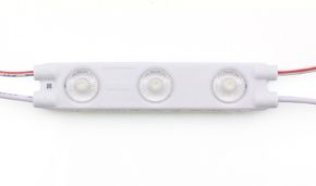
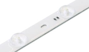
Phosphor layer degradation (for white LEDs)
External and system-level causes accelerating degradation
Junction temperature (Tj): the dominant factor
Junction temperature (Tj) Relative degradation rate* Estimated useful life (L70)** Flux loss after 25,000h* 65°C 1.0 (Reference) > 100,000 h < 5% 85°C 2.5 - 4.0 60,000 - 80,000 h 10 - 15% 105°C 6.0 - 10.0 35,000 - 50,000 h 20 - 30% 125°C 15.0 - 25.0 15,000 - 25,000 h 35 - 50% 145°C 40.0+ < 10,000 h > 70% Drive current: overcurrent and ripple, enemies of luminous flux
Environmental factors: humidity, corrosive gases, radiation
Useful life, standards and degradation projections for luminous flux
Fundamental standards: IESNA LM-80 and IES TM-21
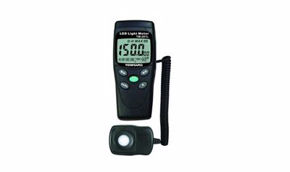
IES LM-80: measurement method for lumen maintenance
IES TM-21: method for projecting useful life from LM-80 data
LM-80 data duration Maximum allowed projection (TM-21) Practical meaning 6,000 hours 36,000 hours (~4.1 years) Basic projection, common but with greater uncertainty margin. 10,000 hours 60,000 hours (~6.8 years) Medium-high reliability projection, indicator of manufacturer quality. 12,000 hours 72,000 hours (~8.2 years) High-reliability projection, typical of professional/industrial products. 15,000 hours 90,000 hours (~10.3 years) Excellence projection, for critical applications or where replacement costs are prohibitive.
Interpretation of Lxx curves and useful life parameters
Definitions of L70, L80, L90 and L50
Lamp Lumen Maintenance Factor (LLMF) in lighting design calculations
Prevention and mitigation strategies for degradation
Thermal management: the undisputed pillar of longevity
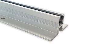
Heat sink design: materials, geometry and surface
Thermal interface (TIM - Thermal Interface Material)
Critical component selection: beyond the LED chip
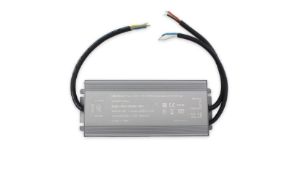
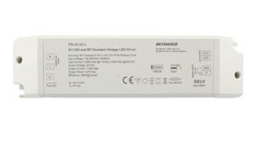
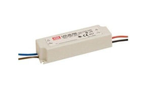
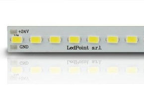
LED drivers: stability, ripple and protections
Primary and secondary optics: resistant materials
Operational strategies: dimming and load management
Thermal derating and dimming
Active temperature management (Thermal Foldback)
Case studies – Analysis and solutions for specific environments
Case study 1: Open-plan office lighting – Differential degradation
Case study 2: Coastal street LED lighting
Critical environment Main degradation agents Specific prevention strategies Recommended materials/Classes Chemical industry (H2S, Solvents) Corrosive gases, oily deposits Absolute hermetic sealing, inert materials, air filters for cooling (if ventilated), frequent cleaning. Stainless steel 316L, aluminum with epoxy paint, Viton gaskets, glass optics. Refrigerators/freezers (-30°C) Cyclic condensation, thermal shock, cold start Drivers with low-temperature start capability, heaters for driver compartment, thermally shock-resistant materials. Thick PCB, wide-temperature-range electronic components (-40°C), flexible optical silicone. Tunnels (dust, exhaust fumes) Particulate deposition on optics, NOx/SOx corrosion, vibrations Design with easily accessible optics for cleaning, IP6K9K rating for high-pressure water cleaning jets, anti-vibration fasteners. Thick aluminum, quick-release lever locking systems.
Predictive maintenance and installation condition monitoring
Integrated monitoring systems (IoT for Lighting)
Monitorable parameters
Data analysis and advanced predictive models
Dashboard and alerting
Integration with maintenance plans (CMMS)
Best practices summary
Decalogue of design and management for maximum longevity
Luminous flux: a more performant future